Protection - power – Basler Electric BE1-11m User Manual
Page 574
562
9424200996 Rev L
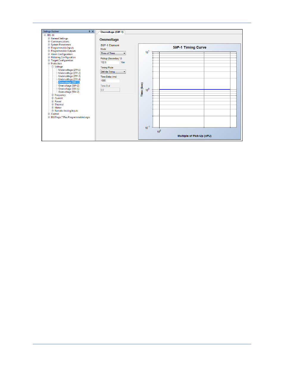
Figure 397. Protection, Voltage, Overvoltage (59P-1) Screen
Protection - Power
A synchronous motor is started by a prime mover, by a “pony motor,” induction motor methods (shorted
field windings, squirrel cage type winding—amortisseur or damper winding) or other means to achieve
near synchronous speed. Applying the external rotor excitation, the rotor locks its speed with the rotating
stator magnetic field; now the motor shaft is rotating at synchronous speed and the machine produces
usable motor torque. The motor power factor is at unity (1.0). See the synchronous motor V curves in
Figure 369.
If too much load is applied to the motor, the power factor begins to drift from unity. Adding more loads
causes the rotor to go out of step with the rotating magnetic field and no shaft torque is developed (if no
additional excitation is added). At this point the synchronous motor stops.
When the motor power factor cannot be maintained at the manufacturer’s specification the motor should
trip; in this case 0.9 PF lagging.
A unique capability of a synchronous motor is that it can provide var support and improve the power
system total power factor; this operation mode is also known as a synchronous condenser. In fact, it can
be operated with variable excitation to produce a leading power factor (overexcited is a variable capacitor
and underexcited is a variable inductor), further stabilizing the power system power factor. In practice, the
field excitation is varied to maintain a constant terminal voltage across a load, so the synchronous motor
behaves as a type of voltage regulator.
The Power Factor (55) element operates during synchronous motor operation. To ensure that the element
is operates only when the motor is in synchronous mode, the logic timer shown in Figure 406 is added to
the element Block input. Figure 398 shows a delay of 1 second. Zero (0) or more delay can be set for
your particular situation.
As shown in the synchronous motor V curves (Figure 369) the motor power factor at 1 p.u. load can begin
to threaten maintained operation of the motor. This condition occurs at 0.85 pf leading.
Configure the Power Factor (55) element as shown in Figure 399. A slight delay allows automatic
excitation equipment or a remedial action scheme an opportunity to correct an out-of-range operation
condition.
Set the Lagging Pickup to 0.90, Leading Pickup to 0.85, and Time Delay to 5 seconds (5000 ms).
Settings Calculation Examples
BE1-11m