1 allocations and configuration definitions, 1 motion module allocation method, Module allocations – Yaskawa MP920 Motion Module User Manual
Page 110: Module configuration example
3 Motion Module Allocations and Setup
3.1.1 Motion Module Allocation Method
3-2
3.1
Allocations and Configuration Definitions
This section describes the MP920 Motion Module allocation method and the configuration def-
inition procedure.
3.1.1
Motion Module Allocation Method
Module Allocations
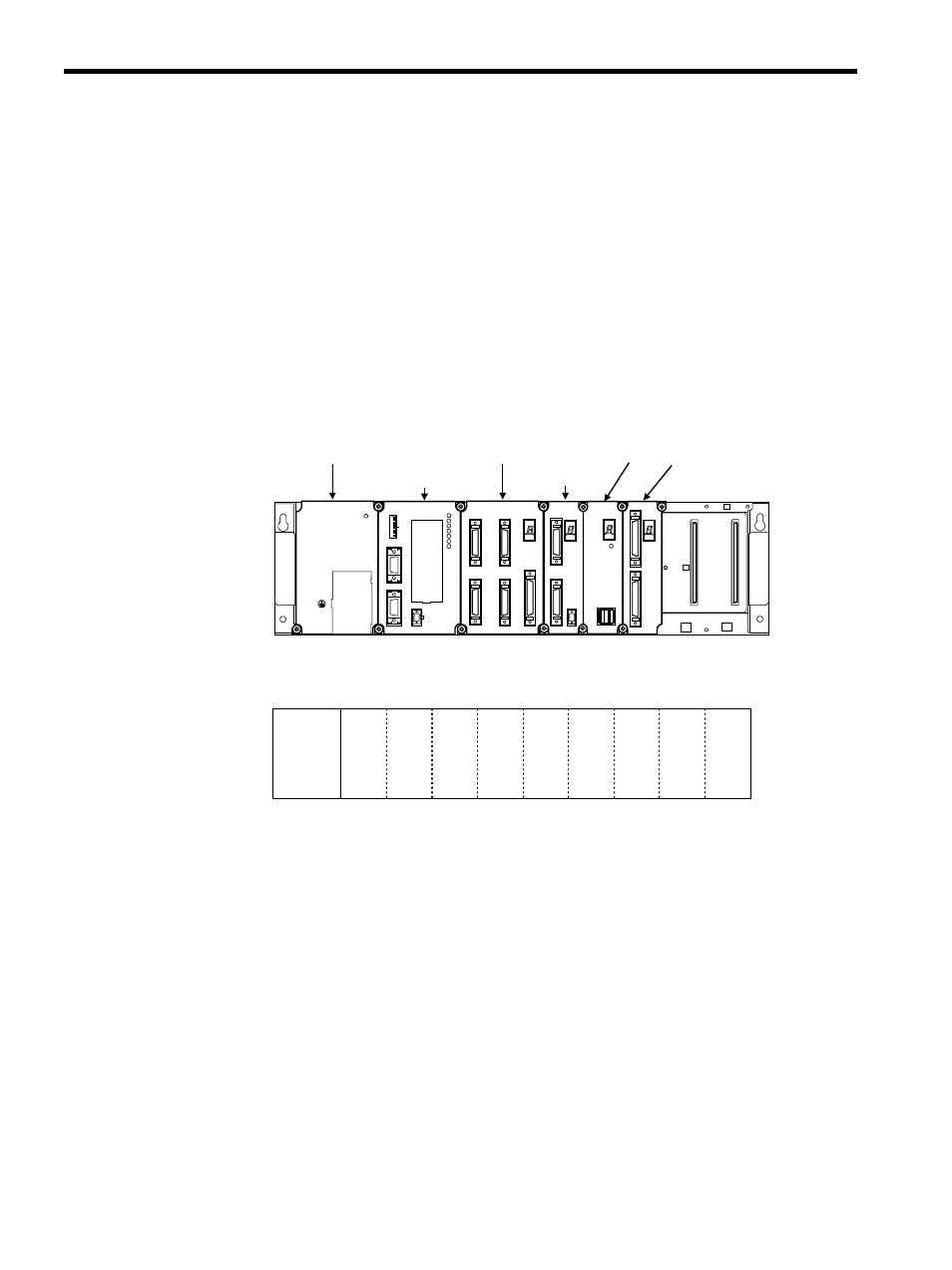
Make allocations for the MP920 Modules on the Mounting Base as shown below, then
define the system configuration.
Module Configuration Example
The following configuration definition procedure applies when these Modules are allocated
using the MB-01 Long Rack.
CPU
Module
SVA-02A
Module
SVA-01A
Module
SVB-01
Module
PO-01
Module
PO-01
CN1
CN2
STATUS
SVB-01
STATUS
TRX
CN1
CN1
CN2
SVA-02A
STATUS
CN3
+24V
0V
SVA-01A
CN1
CN3
CN2
CN4
STATUS
CN5
SW1
L.RST
RUN
INIT
TEST
MULTI
FLASH
M.RST
ON
OFF
ON
12
34
56
78
PORT2
PORT1
CN1
RLY OUT
BATTERY
RDY
PRT1
RUN
ALM
ERR
BAT
ALM
PRT2
MP920 CPU-01
PS-03
DC24V
POWER
TB1
+24V
0V
FG
SG
Power Supply
Module
PS
Slot
(Long Rack)
0
1
2
3
4
5
6
7
8