Yaskawa MP920 Motion Module User Manual
Page 219
5.4 SVA-01A and SVA-02A Parameters
5-77
5
34
Motion Com-
mand Control
Flag
(MCMDCTRL)
(cont’d)
Bit 13
Forward Limit
Signal for Zero
Point Return
(LMT_R)
This bit functions as a forward limit signal when return-
ing to the zero point (ZRET). The external signal (DI sig-
nal input by the LIO-01 or other Module) in the user
program must be connected (i.e., programmed) to
OB21D.
0
Bit 14
Position Buffer
Write (BUF_W)
Data set in OL3A: Position Buffer Write Data is
stored as absolute position data in the position buffer that
is set at OL38: Position Buffer Access Number.
0
Bit 15
Position Buffer
Read (BUF_R)
Used to check position data that is stored in the position
buffer.
Data from the position buffer that is specified at
OL38: Position Buffer Access Number is stored as
absolute position data in the position buffer that is set at
IL28: Position Buffer Read Data. It takes two scans
from the time the Position Buffer Read command is
issued until the data is stored at IL28: Position Buffer
Read Data.
0
35
Rapid Traverse
Speed (RV)
OL22
0 to 2
31
-1
Used when an OW20: Motion Command Code is
used in Position Control Mode.
Set the rapid traverse speed in 10
n
reference units/min (n:
Number of digits below decimal point) if OB01D:
Speed Reference Selection is set to “0.”
Other setting units are expressed as follows:
Pulse unit: 1 = 1000 pulses/min
mm unit: 1 = 1 mm/min
deg unit: 1 = 1 deg/min
Inch unit: 1 = 1 inch/min
3000
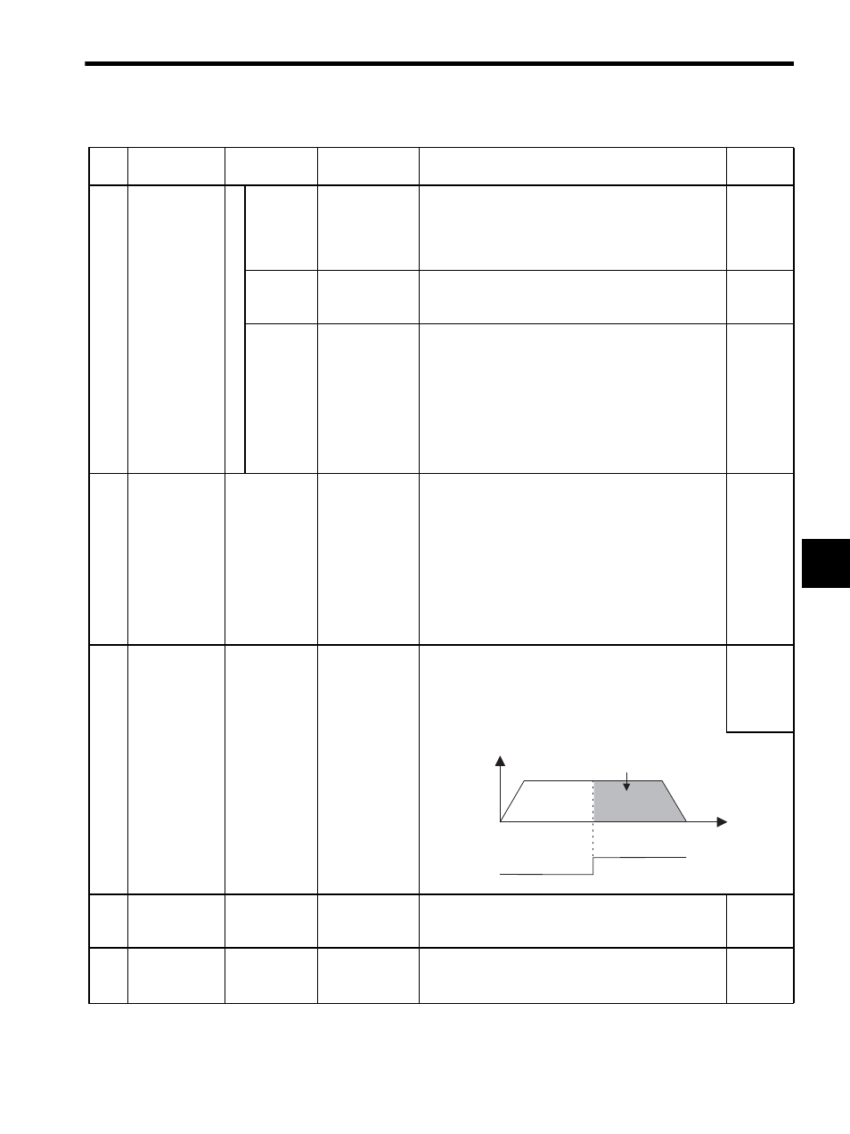
37
External Posi-
tioning Travel
Distance
(EXMDIST)
OL24
-2
31
to 2
31
-1
Used when an OW20: Motion Command Code is
used in Position Control Mode.
Set the distance from the time the latch signal (external
positioning signal) is input until the machine stops during
external positioning (EX_POSING).
0
39
Stopping
Distance
(STOPDIST)
OL26
-2
31
to 2
31
-1
Used by the system. Do not use it.
0
41
Step Travel
Distance
(STEP)
OL28
0 to 2
31
-1
Set the travel distance in reference units for Step execu-
tion for the OW20: Motion Command Code.
• Unit: Reference unit
0
Table 5.6 Motion Setting Parameters (cont’d)
No.
Name
Register
Number
Setting Range/
Bit Name
Description
Factory
Setting
v
External positioning travel
distance
Latch signal
t