2 interval counter mode – Yaskawa MP920 Motion Module User Manual
Page 425
10 CNTR-01 Module Specifications and Handling
10.3.2 Interval Counter Mode
10-24
10.3.2
Interval Counter Mode
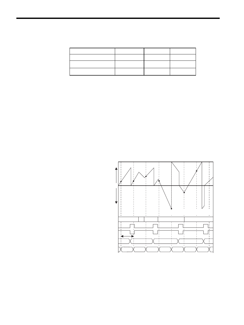
The Interval Counter Mode increments and decrements the count according to pulse A and
pulse B inputs. In this mode, the count will be latched on the rising edge of pulse C to reset
the counter. The latched interval count is stored in the input register each scan. The current
counter value is stored as the current hardware counter value.
The following functions are possible in Interval Counter Mode depending on output register
designations.
• Count Prohibit: Disables counting.
• Coincidence Detection: Outputs an external output signal when the Set Coincidence
Detection output register value and the current counter value are the same.
* 1. Current counter value = Hardware counter (IL + 4)
* 2. Interval counter value = Interval data (OL + 6)
Table 10.5 Output Data
Name
Register No.
Range
Meaning
Operating Mode
OW
Each bit
−
Count Preset Data
OL + 2
0 to
± 2
31
-1
1 = 1 pulse
Set Coincident Detection
OL + 4
0 to
± 2
31
-1
1 = 1 pulse
n1
n2
n3
n4
n5
n6
n7
n1
n2
n3
n4
n5
n6
n7
UP
Ts
0
(+)
(-)
m0
m1
m2
m3
m4
DOWN
UP
DOWN
UP
m2
m3
m4
MIN
(80000000H)
MIN
(80000000H)
Ts: Scan setting
MAX (7FFFFFFFH) MAX (7FFFFFFFH)
Count register
Pulse A and pulse B
Pulse-C terminal (positive logic)
Pulse-C terminal (negative logic)
Interval counter value
*2
Current counter value
*1