Yaskawa MP920 Motion Module User Manual
Page 50
2 Motion Control
2.2.5 Zero Point Return Mode
2-24
* Valid only with an SVA-02A Module.
In the example, the SERVOPACK is used as axis 1 of Module No. 1. When the Module
number and the axis number are different, see 4.1.2 Modules and Motion Parameter
Registers, and change the register number.
3. Set the Zero Point Return Mode (ZRN) to ON (bit 4 of OW00).
4. To start operation, set the RUN Servo ON (RUN) to ON (bit 0 of OW01).
The axis will be moved in the direction specified by the Zero Point Return Direction
Selection ZRNDIR (bit 9 of OW00).
a) When the Zero Point Return Deceleration Point Limit Switch LSDEC (bit 15 of
OW01) turns ON, the axis is decelerated to creep speed.
A user program must be created to connect the Limit Switch Signal DECLS (the DI signal included in
the LIO-01 Module) to the Zero Point Return Deceleration Point Limit Switch LSDEC (bit 15 of
OW01).
b) When LSDEC turns from ON to OFF, the point detected by the initial zero point
pulse (Phase-C pulse) is the zero point position. The axis is decelerated to a stop after
detecting the initial zero point pulse.
c) After decelerating to a stop, the axis is moved only the zero point overtravel distance
at creep speed in the zero point position direction and stops at the zero point position.
A zero point position offset value can also be set. (If Machine Coordinate System
Zero Point Position Offset OL06 is set in advance to 100, the position data will
be 100.)
d) The zero point return operation is completed when the axis enters the positioning
completed range. When the zero point return operation is completed, the Zero Point
Return Completed Signal ZRNC (bit 15 of IW00) turns ON.
5. After checking that the zero point return completion signal (ZRNC) is turned ON, set
the RUN command (RUN) and the zero return mode (ZRN) to OFF.
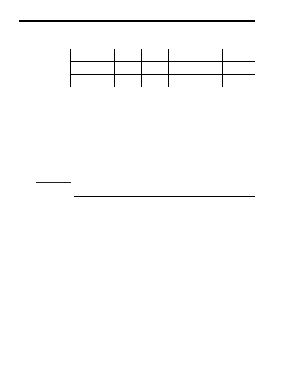
Position Loop Gain
Setting (KP)
OW10
0.0 to 3276.7 0.1 = 0.1 /s
1 = 1 /s
30.0
(30.0 /s)
Filter Time Constant
(NNUM)
OW14
0 to 255
For simple S-curved
acceleration
0
Table 2.8 Examples of Setting Parameters (cont’d)
Name
Register No.
Setting
Range
Meaning
Setting
Example
IMPORTANT