4 out-of-step detection, Module configuration example, Out-of-step detection procedure – Yaskawa MP920 Motion Module User Manual
Page 327
7.2 Functions
7-25
7
7.2.4
Out-of-step Detection
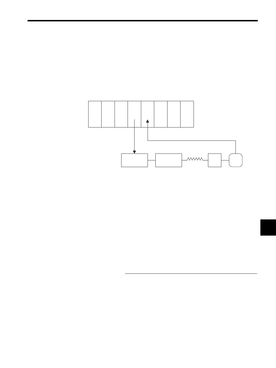
Module Configuration Example
Use the MP920 Counter Module (CNTR-01) to detect out-of-step operation with the pro-
gram shown in DWG.H.
The following figure shows an example of Module configuration.
Fig. 7.4 Example of a Module Configuration for Out-of-step Detection
Out-of-step Detection Procedure
Out-of-step operation is detected by converting the pulse motor position reference (calcu-
lated feedback position: P
i
) from the counter value (FB position: N
i
) at the Counter Module
(CNTR-01) and then determining the difference between that calculation result (P
i
) and the
reference position (M
i
).
The feedback position (P
i
) is calculated using the number of incremental pulses per scan and
the counter value from the CNTR-01 Module to handle infinite length positioning as well.
The following equation is used for this calculation.
• Reference position: M
i
= M
i-1
+ number of pulses output per scan (IL2A of PO-01)
•
N: Number of encoder pulses per Servomotor rotation
M: Number of reference pulses per Servomotor rotation
n:
Encoder pulse multiplier (n = 1, 2, 4)
Therefore, the following situation is considered out of step.
• |M
i
- P
i
| >
ε (ε = error width user setting)
Use the PO-01 Module monitor parameter for number of output pulses in XREFMON:
IL2A for Mi. Use the number of incremental pulses per scan in PDV: IL + 2
from the Counter Module input data for the number of incremental pulses per scan.
PS
CPU
PO-01 CNTR
-01
Pulse motor
driver
Pulse motor
Machine
PG
MP920
Encoder pulse
Pulse train
FB position: P
i
=
P
i-1
+ number of incremental pulses per scan (IL
2)
×
M + the remainder
n
×
N