4 sgdm/sgds servopack connections, Connection example, Parameter settings – Yaskawa MP920 Motion Module User Manual
Page 388
9 Application Precautions
9.1.4 SGDM/SGDS SERVOPACK Connections
9-8
9.1.4
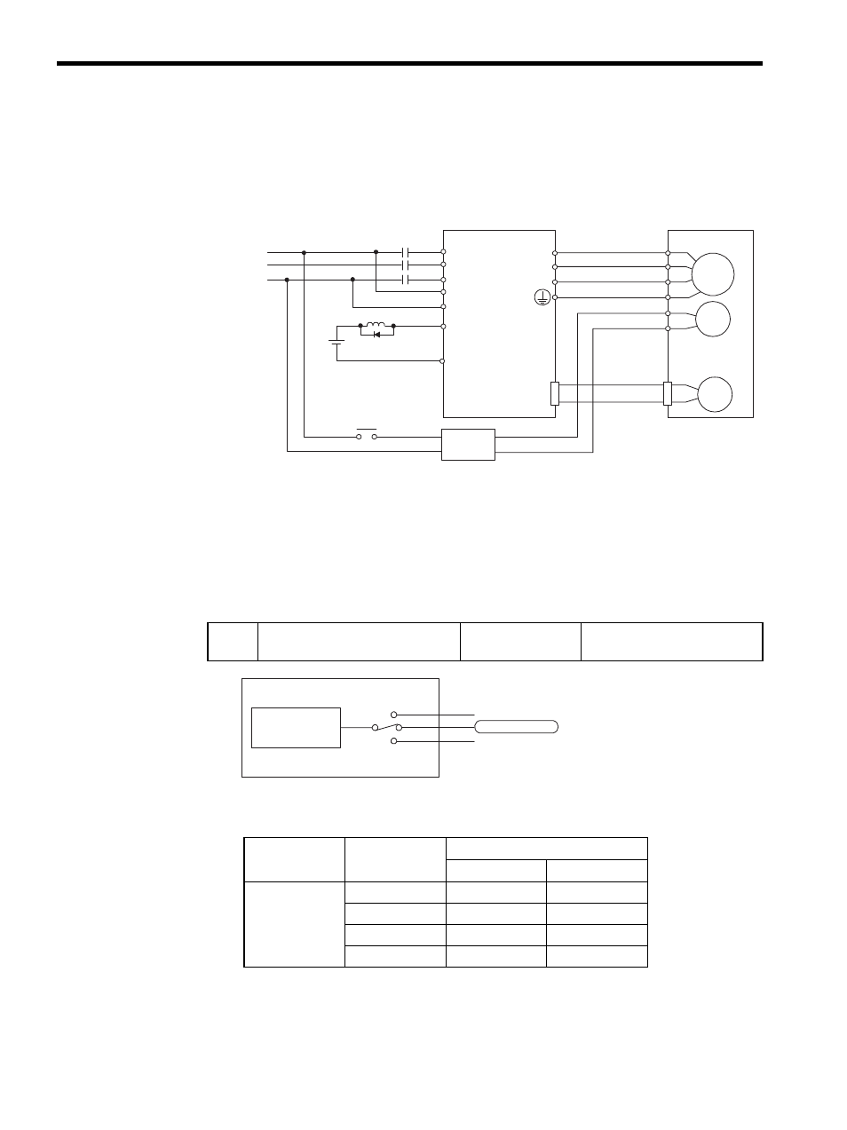
SGDM/SGDS SERVOPACK Connections
Connection Example
* 1. Parameter PN50F. 2 is the allocated output terminal number.
* 2. Brake control relay
* 3. Brake power supplies are available in either 200 or 100-V models.
Parameter Settings
The following parameter setting selects which 1CN pin will output the BK signal.
Selects which terminal will output /BK. (Set 2.)
M
BK
PG
U
V
W
CN2
AC
DC
BK-RY
BK-RY
+24 V
L1
L2
L3
L1C
L2C
SGDM/SGDS SERVOPACK
27-
*1
*1
28-
/BK+
/BK-
A(1)
B(2)
C(3)
D(4)
E(5)
F(6)
Power supply
Blue or yellow
White
Red
Black
Servomotor
with brake
*2
Brake power supply
*3
Pn50F Output Signal Selection 2
Factory Setting:
0
Speed/torque control and
position control
Parameter No.
Setting
Output Terminal (CN1)
1
2
Pn50F.2
0
−
−
1
25
26
2
27
28
3
29
30
/BK brake
interlock output
Pn50F.2
1
2
3
Input terminal
CN1-25,26(SO1)
CN1-27,28(SO2)
CN1-29,30(SO3)