Cn1 connection, Connection and external view of standard cables, Important – Yaskawa MP920 Motion Module User Manual
Page 241
6 SVB Module Specifications and Handling
6.1.2 Handling
6-6
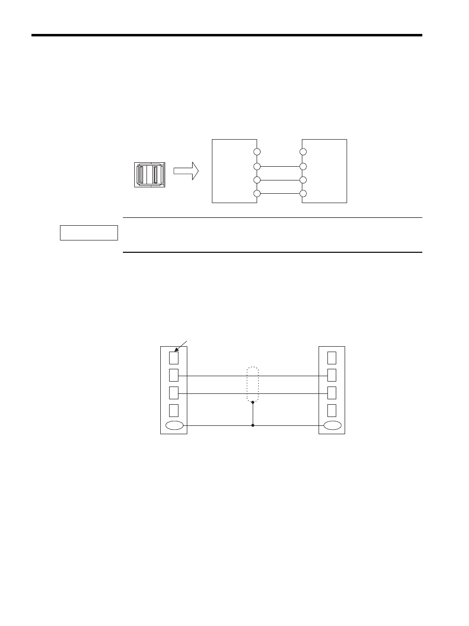
CN1 Connection
The right and left CN1 connector ports are identical. The cable end can be inserted into
either of these ports.
Insert the USB Terminator (JEPMC-W6020) into the unused port.
The SVB-01 Modules has a MECHATROLINK port for only one channel. Use either of the two con-
nectors.
Connection and External View of Standard Cables
The internal cable connection between the SVB-01 Modules and the I/O Unit (IO350) is
shown in the following figure.
Note: A divided core is attached to the cable model JEPMC-W6001-.
The following figure shows internal MECHATROLINK cable connections when multiple
SERVOPACKs are connected to an SVB-01 Module (1: N cable connections).
1
2
3
4
1
2
3
4
(NC)
(NC)
SH
SH
CN1
DATA
DATA
/DATA
/DATA
IMPORTANT
1
2
3
4
Shell
1
2
3
4
Shell
Pin No.
Name
(NC)
/DATA
DATA
SH
Shield
Name
(NC)
/DATA
DATA
SH
Shield
Cable model: JEPMC-W6000-A3
JEPMC-W6001-