Led indicator alarm displays – Yaskawa MP920 Motion Module User Manual
Page 380
8 Troubleshooting
8.2.3 Motion Module Error Displays and Actions Taken
8-24
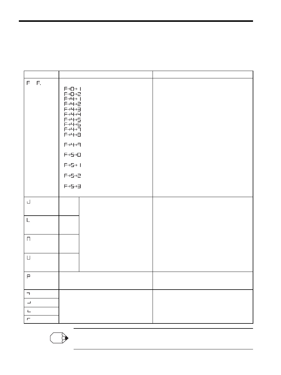
LED Indicator Alarm Displays
When an error or alarm occurs, refer to the following table.
The above alarm displays are applicable to the SVA-01A Module only. For alarm displays of other
Modules, refer to LED Indicator in Chapters 5, Chapters 6, and Chapters 7.
Table 8.4 LED Indicator Alarm Displays
Display
Meaning
Remedy
or
followed by
error code
A Motion Module hardware error has occurred. Replace
the Module.
1. A watchdog time over error may occur when the user
program processing time exceeds the scan time set-
ting. Check the user program and the scan time set-
ting.
2. A synchronization error indicates a problem with
synchronization between the PLC (CPU1/CPU2)
and a Servo Module. Check the error contents of the
CPU Module. If they are normal, replace racks and
Modules one at a time to isolate the cause of the
problem.
Note: The alarm displays shown here are applicable
to SVA-01A, SVA-02A, and PO-01 Modules.
Axis 1
Alarm (SVRDY “ON”)
1. Error fault
2. Setting parameter setting error
Abnormal (SVRDY “OFF”)
1. Fixed parameter setting error
2. Absolute encoder interface error
Check the contents of IW00 + the axis offset to
determine which of the items shown on the left is the
cause of the problem.
A setting parameter setting error indicates that any of the
values specified in the setting parameters are outside the
allowable range. Check the setting parameter settings,
and correct them as necessary.
A fixed parameter setting error indicates that any of the
values specified in the fixed parameters are outside the
allowable range. Check the fixed parameter settings, and
correct them as necessary.
For an absolute encoder interface error, initialize the
absolute encoder.
Axis 2
Axis 3
Axis 4
Operation of other CPU stops
Some other Module is stopped. Check other Modules.
For example, check whether the PLC (CPU1/CPU2) is
stopped.
Absolute position reading retry status
A retry has been performed for absolute positioning read
processing during initialization executed by turning ON
or resetting the system when fixed parameter No. 3
(Encoder Selection) is set to 1 (Absolute Encoder).
: Watchdog time over
: Synchronization error
: ROM diagnosis error
: RAM diagnosis error
: Shared memory diagnosis error
: Built-in CPU timer diagnosis error
: Timer diagnosis error
: NVRAM read error
: NVRAM write error
: General illeagal instruction interrup-
tion occurrence
: Slot illegal instruction interrupition
occurrence
: CPU address error interruption oc-
currence
: DMA address error interruption
occurrence
: User break interruption occur-
rence
: Trap instruction interrup-
tion occurrence
Serious fault (operation stop)
INFO