Supplemental explanation 2 – Yaskawa MP920 Motion Module User Manual
Page 207
5.4 SVA-01A and SVA-02A Parameters
5-65
5
Supplemental Explanation 2
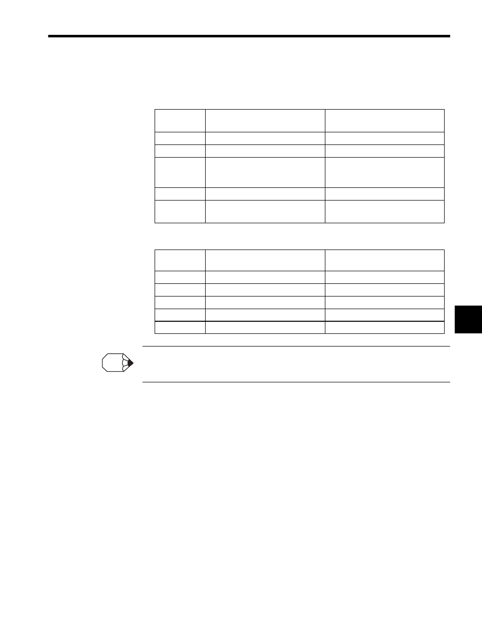
1. SVA-01A (4-axis Servo) Module
2. SVA-02A (2-axis Servo) Module
Refer to 5.1 SVA-01A Module for details on the SVA-01A Module (4-axis Servo Module) connector
and connector pin arrangement.
Name
OW01
Connected to a VS-866
Connected to a SERVOPACK
(SGDA, SGDB)
Bit 0 (DO0)
Run
Servo ON (SV-ON)
Bit 1 (DO1)
Failure reset (RST)
Alarm reset (ALM-RST)
Bit 2 (DO2)
Emergency stop (EMG): Logical
value, i.e., turn OFF to achieve the
operation.
Proportional control (P-CON)
Bit 3 (DO3)
Ready (RDY)
Not used. (ROn)
CN5
Bit 4 (ROC)
Not used.
Not used. (ROC) Only for 1st axis
CN5
Name
Connected to a VS-866
Connected to a SERVOPACK
(SGDA, SGDB)
Bit 0 (DO0)
Run
Servo ON (SV-ON)
Bit 1 (DO1)
Failure reset (RST)
Alarm reset (ALM-RST)
Bit 2 (DO2)
Emergency stop (EMG)
Proportional control (P-CON)
Bit 3 (DO3)
Torque control selection (TSEL)
Forward overtravel (P-OT)
Bit 4 (DO4)
Ready (RDY)
Reverse overtravel (N-OT)
INFO