2 sva-01a module, Overview of the sva-01a module – Yaskawa MP920 Motion Module User Manual
Page 17
1.1 Module Overview and Features
1-3
1
1.1.2
SVA-01A Module
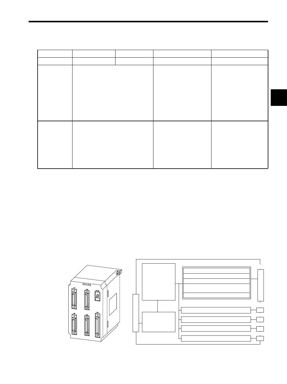
Overview of the SVA-01A Module
The SVA-01A Module is a Motion Control Module with analog outputs. One SVA-01A
Module can control servos for up to four axes. Four connectors (CN1 to CN4) are provided
for connections to SERVOPACKs. Each connector is equipped with a speed reference ana-
log output, phase-A/B/C pulse inputs (5 V differential), a pulse latch digital input, and gen-
eral-purpose digital I/O signals. The CN5 connector is equipped with positive and negative
overtravel signals, deceleration limit inputs, zero point latch inputs, external positioning
latch inputs, brake control outputs, and other external I/O signals for four axes.
Applicable Ser-
vo Drivers and
Inverters
• Servo Drivers
SGDA-S
SGDB-
SGDM-
SGDS-
• Inverters
• Servo Drivers
SGD-N
SGDB-AN
SGDH-E+JUSP-
NS100
• Inverters
(216IF Card required)
VS-616G5
VS-676H5
VS-676H5T
Pulse Motor Drivers
Features
Analog control
High-speed network control
• Transmission speed:
4 Mbps
• Communications cycle: 2 ms
• Transmission distance: 50 m
max.
Multi-axis control:
14 axes max. per Module
Low-cost and simple control
(cont’d)
Description
SVA-01A
SVA-02A
SVB-01
PO-01
Model Number
JEPMC-MC200A
JEPMC-MC220A
JEPMC-MC210
JEPMC-PL210
Motion Control
Speed control
Position control
Phase control
Zero point return
function
Monitor function
Analog output: Speed ref.
Same as above.
Same as above.
Same as above.
External (Field) I/O signals
Pulse input: Phase A/B/C
General-purpose digital inputs (3) DI0 to D12
General-purpose digital outputs (5) DO0 to DO2
DO4, DO5
SENS/DO3
Sensor ON output (5 V/24 V)
NREF
System Bus
Interface
Servo parameters
OW
IW
System Bus Connector
Servo Connector
CN1
CN2
CN3
CN4
CN5