Yaskawa MP920 Motion Module User Manual
Page 253
6 SVB Module Specifications and Handling
6.2.1 Motion Fixed Parameters
6-18
17
Bit 9
Override Selection
(USE-OV)
Set whether or not to use the override function.
(For interpolation related commands, set override in the
register specified in the Group Definition Window.)
0: Disabled
1: Enabled
The OW2C: Override is used when this parameter is
set to Enabled. The override is fixed at 100 if this param-
eter is disabled.
Note: The override function always the feed speed
setting to be modified in an application.
0
(Disabled)
Bits 10 to 11
Not used.
−
−
Bit 12
Servo Drive
Transparent
Command Mode
(THROUMOD)
In this mode, the user can directly execute MECHA-
TROLINK servo commands.
0: Disabled
1: Enabled
For MECHATROLINK servo commands, motion setting
parameters OW30 to OW37 (16 bytes) are used
to send command data, and motion monitoring parame-
ters IW30 to IW37 (16 bytes) are used to
receive response data.
0
(Disabled)
Bits 13 to 14
Not used.
−
−
Bit 15
Interpolation Com-
mand Segment Dis-
tribution Function
Always set this bit to 0 (enabled) when using interpola-
tion-related motion commands (interpolation or interpo-
lation with position detection).
0
(Enabled)
18
Number of Digits Be-
low Decimal Point
(DECNUM)
Set the number of digits to the right of the decimal point in input reference units.
The minimum reference unit is determined by this parameter and Reference Unit
Selection in the Motion Controller Function Selection Flags (bit 0 to bit 3).
3
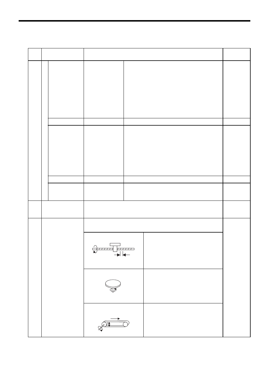
19
Travel Distance Per
Machine Rotation
(PITCH)
Set the load travel distance (reference unit) per load axis rotation.
• Setting range: 1 to 2
31
-1
10000
Ball screw
Ball screw pitch = 10 mm
Reference Unit Selection = mm
Number of digits below decimal point = 3
↓
Set the travel distance per machine rotation
to 10000.
Rotating table
One table rotation = 360
°
Reference Unit Selection = deg
Number of digits below decimal point = 3
↓
Set the travel distance per machine rotation
to 360000.
Belt
One roller rotation = 360
°
Reference Unit Selection = mm
Number of digits below decimal point = 3
↓
Set the travel distance per machine rotation
to
πD × 1000.
Table 6.2 Motion Fixed Parameters (cont’d)
No.
Name
Description
Factory
Setting
10
Ball screw pitch = 10 mm
One rotation = 360
°
D
π D