Module configuration – Yaskawa MP920 Motion Module User Manual
Page 413
10 CNTR-01 Module Specifications and Handling
10.2.1 Overview
10-12
Module Configuration
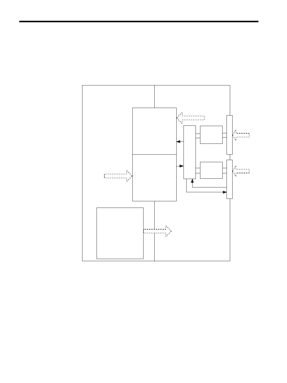
The Counter Module executes the functions specified in fixed parameters and output regis-
ters, and outputs status information and counter values to input registers.
The following illustration shows data flow for the CNTR-01 Module.
CPU-01 Module
Shared Memory
Data from CNTR-01
Module to CPU Module
CN1
Pulse input
Pulse input
CN2
CNTR-01 Module
5-V
differential
interface
12-V
voltage
interface
Latch input
Output
Coincidence detection
Fixed Parameters
Reference from CPU-01
Module to Counter
Module
Input Registers
(16 words per channel)
Operating status
Incremental pulses
Hardware counter
Latch data, etc.
Average frequency
Output Registers
(16 words per channel)
Operating mode
Averaging count
settings
Preset count data
Coincidence detection
settings
Counter Module
Operating Conditions
Leading register
numbers
Pulse-A/B/C signal type
selection
Pulse-A/B/C signal
polarity selection
Pulse counting method
Counter mode
Other function
selections
Pulse Input Processor