Yaskawa MP920 Motion Module User Manual
Page 173
5.2 SVA-02A Module
5-31
5
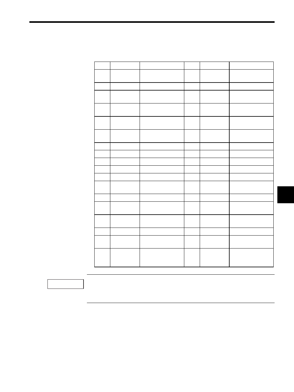
The following table shows the name and function of the pins of the CN1 and CN2 connec-
tors.
Both 5 V and 24 V can be used for the SEN signal. Connect power to either pin 20 or pin 32 according
to the application.
The standard cable is connected to 5 V (pin 20).
Pin
Signal Name
Function
Pin
Signal Name
Function
1
SG
Ground (for analog)
19
SG
Ground
(for SEN signal)
2
NREF
Speed reference
20
SEN (5V)
SEN signal
3
PA
5-V differential pulse
input (+)
21
Not used.
−
4
PAL
5-V differential pulse
input (-)
22
Not used.
−
5
PC (5V)
5-V differential pulse
input (+)
23
PB
5-V differential Pulse-
B terminal (+)
6
PCL (5V)
5-V differential pulse
input (-)
24
PBL
5-V differential Pulse-
B terminal (-)
7
SG
Ground
25
SG
Ground
8
AI-IN
Analog input
26
AI-GND
Analog input ground
9
AO-OUT
Analog output
27
AO-GND
Analog output ground
10
0V (24V)
0 V (24 V)
28
0V (24V)
0 V (24 V)
11
0V (24V)
0 V (24 V)
29
0V (24V)
0 V (24 V)
12
PCON
P operation reference,
DO2
30
ALM RST
Alarm reset, DO-1
13
OTR
Overtravel (-) DO-4
31
SV ON
Servo ON, DO-0
14
OTF
Overtravel (+) DO-3
32
SEN (24V)
SEN output for VS-
866
15
General-
purpose DI
General-purpose input
(OTF) DI-3
33
General-
purpose DI
General-purpose input
(OTR) DI-4
16
+24V
+24 V power supply
34
+24V
+24 V power supply
17
SV ALM
Servo alarm input,
DI-0
35
SRDY
Servo ready input,
DI-1
18
BRK
Brake ON input, DI-2
36
General-
purpose DI
General-purpose input
DI-5 (External posi-
tioning latch)
IMPORTANT