Yaskawa MP920 Motion Module User Manual
Page 88
2 Motion Control
2.4.4 Zero Point Return (ZRET)
2-62
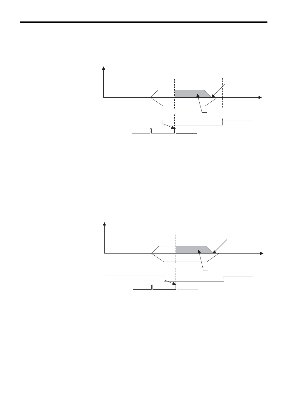
Zero Point Return Operation Started and Interval (c) Used
1. The axis travels at approach speed in the reverse direction.
2. The axis decelerates at the rising edge of the dog (deceleration limit switch) signal.
3. The axis travels at creep speed in the forward direction.
4. After the falling edge of the dog (deceleration limit switch) is detected, the axis stops
after traveling only the zero point return final travel distance (OL2A) from the ini-
tial zero point signal, and that position will be the machine coordinate system zero point.
Zero Point Return Operation Started and Intervals (d) & (e) Used
1. The axis travels at approach speed in the reverse direction.
2. The axis decelerates at the rising edge of the dog (deceleration limit switch) signal.
3. The axis travels at creep speed in the forward direction.
4. After the falling edge of the dog (deceleration limit switch) is detected, the axis stops
after traveling only the zero point return final travel distance from the initial zero point
signal, and that position will be the machine coordinate system zero point.
0
3.
2.
1.
4.
Speed
reference
Dog
(Deceleration limit switch)
Zero point signal
(Phase-C pulse)
Creep speed
Approach speed
Zero point
Zero point
return position
Time
Zero point return
final travel distance
Reverse direction
← → Forward direction
0
3.
2.
1.
4.
Speed
reference
Dog
(Deceleration limit switch)
Zero point signal
(Phase-C pulse)
Creep speed
Approach speed
Zero point
Zero point
return position
Time
Zero point return
final travel distance
Reverse direction
← → Forward direction