3 setting i/o data – Yaskawa MP920 Motion Module User Manual
Page 416
10.2 Using the CNTR-01 Module
10-15
10
10.2.3
Setting I/O Data
I/O data includes data reported by the Counter Module, operating status data, and settings
and request flags sent to the Counter Module as references.
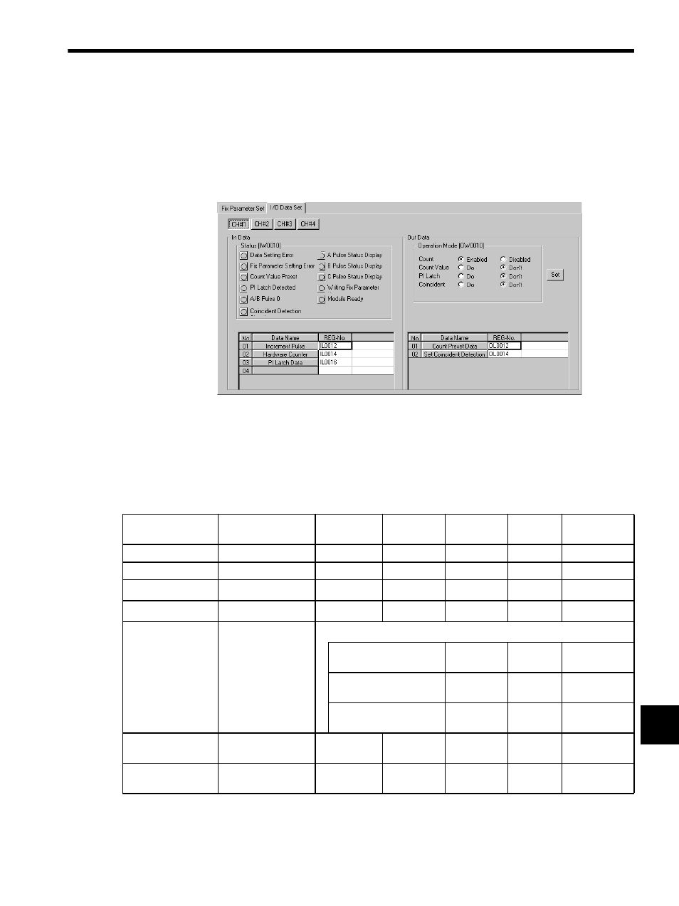
The I/O Data Setting Window is shown below.
The contents of I/O data is described below.
In Data (Input Data)
Input data is reported by the Counter Module to the CPU Module. It is stored in the input
registers of the CPU Module at the beginning of each scan.
Note:
√: Supported, −: Not supported
Name
Register Number
Range
Meaning
Reversible
Counter
Interval
Counter
Frequency
Measurement
Status
IW
Each bit
−
√
√
√
Reserve
IW + 1
−
−
−
−
−
Increment Pulse
IL + 2
0 to
±
2
31
-1
1 = 1 pulse
√
−
√
Hardware Counter
IL + 4
0 to
±
2
31
-1
1 = 1 pulse
√
√
√
PI Latch Data,
Interval Data, or
Detected
Frequency
IL + 6
0 to
±
2
31
-1
1 = 1 pulse
Reversible Counter:
PI Latch Data
√
−
−
Interval Counter:
Interval Data
−
√
−
Frequency Measurement:
Detected Frequency
−
−
√
Average
Frequency
IL + 8
0 to
±
2
31
-1
1 = 1 pulse
−
−
√
Reserve
IW + A to
IW + F
−
−
−
−
−