Ladder logic program example – Yaskawa MP920 Motion Module User Manual
Page 95
2.4 Position Control Using Motion Commands
2-69
2
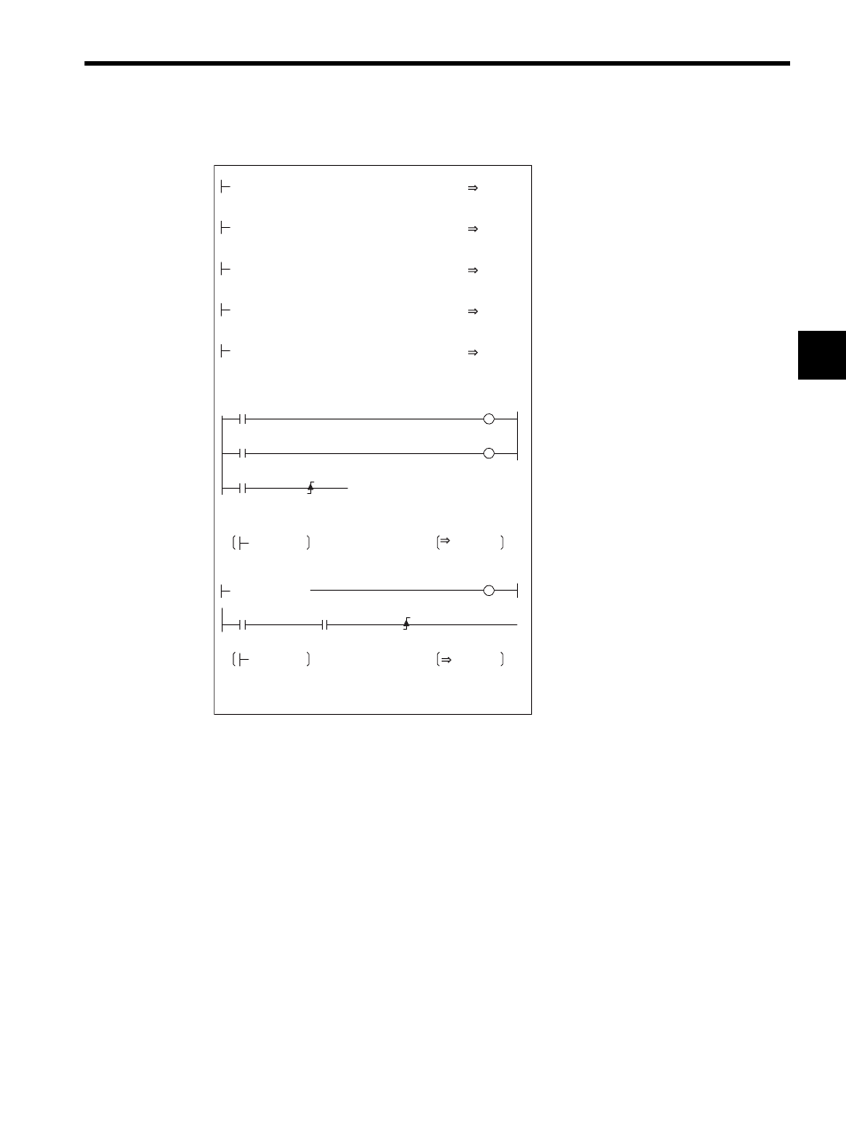
Ladder Logic Program Example
Fig. 2.20 Zero Point Return Programming Example (DWG H03)
* For the SVB-01 Module, set the zero point return final distance to the
value of the SERVOPACK parameter.
The example in the above illustration has been greatly simplified. In actual operation, each
register can be controlled from the user program.
00003
IB00000
S-ON
OBC0010
IB00001
DB000001
DEND
H0104
RUNMOD
OWC000
05000
RV
OLC023
02000
Napr
OWC00A
00500
Nclp
OWC00B
IB00002
LSDEC
OBC001F
OWC020
IWC014=00003
DB000000
DB000000
IBC0156
DB000002
00000
OWC020
00100
ZRNDIST
OLC02A
Set the position control mode to ON.
Rapid traverse speed (RV)
(5,000,000 pulses/min)
Approach speed (Napr)
(2,000,000 pulses/min)
Creep speed (Nclp)
(5,000,000 pulses/min)
Zero point return final travel distance*
(100 pulses)
Servo ON command
IB0002: Limit switch signal
When the zero point return switch (IB00002)
is turned ON, the Zero Point Return
command is executed on the rising edge.
When zero point return is completed, the zero
point return completed status (IBC0156) turns
ON.
When the zero point return is completed status
(IBC0156) turns ON, set NOP (= 0) in the
motion command code.