Yaskawa MP920 Motion Module User Manual
Page 232
5 SVA Module Specifications and Handling
5.4.3 Motion Monitoring Parameters
5-90
24
Position Con-
trol Status
(POSSTS)
(cont’d)
Bit 4
Preset Request
for Number of
POSMAX Turns
Completed
(TPRSE)
Turns ON when OB2D1: Request for Preset Number of POS-
MAX Turns is ON and presetting has been completed. It turns OFF
when OB2D1: Request for Preset Number of POSMAX Turns
goes OFF.
It is valid when infinite length axis is set.
Bit 5
Electronic Gear
Enabled Selec-
tion (GEARM)
Indicates the electronic gear enabled selection at bit 4 of motion fixed
parameter No. 17.
Bit 6
Axis Selection
(MODSELM)
Indicates the axis selection at bit 5 of motion fixed parameter No. 17.
Bits 7 to 15 Not used.
−
25
Machine Coor-
dinate System
Reference Po-
sition (MPOS)
IL18
-2
31
to 2
31
-1
This parameter is the reference position in the machine coordinate sys-
tem and is basically the same value at IL02 (CPOS). This position
data cannot be updated if IB170: Machine Locked is ON.
It is valid in Position Control Mode when an OW20: Motion
Command Code is used.
27
Not used.
IL1A
−
−
29
POSMAX
Monitor
(PMAXTURN)
IL1C
1 to 2
31
-1
Indicates the infinite length axis reset position (POSMAX) at motion
fixed parameter No. 23.
It is valid in Position Control Mode when an OW20: Motion
Command Code is used.
31
Number of
POSMAX
Turns
(PMAXTURN)
IL1E
-2
31
to 2
31
-1
The count at this parameter goes up and down every time the reset
position (POSMAX) for the infinite length axis at motion fixed
parameter No. 23 is exceeded.
The parameter can be preset with OL30: Preset Number of POS-
MAX Turns and with OB2D1: Request for Preset Number of
POSMAX Turns.
It is valid in Position Control Mode when an OW20: Motion
Command Code is used.
33
Not used.
IL20
−
−
35
Alarms
(ALARM)
IL22
This parameter is valid in Position Control Mode when an OW20: Motion Command
Code is used.
Alarm data and a halt to operation are indicated if this register shows anything other than
“0.” The register can be cleared by starting up OB006: Alarm Clear. If an alarm
occurs, the SVA Module indicators will indicate (
) (first axis), (
) (second axis),
(
) (third axis) and (
) (fourth axis). The bit configuration is described below.
Bit 0
Not used.
−
Bit 1
Positive
Overtravel
Turns ON when the positive overtravel signal is input and a move
command is executed in the positive direction.
It is valid if Enabled is selected at bit 13 of Motion Controller Func-
tion Selection Flags: Positive Overtravel Selection is enabled in
motion fixed parameter No. 17.
Bit 2
Negative
Overtravel
Turns ON when the negative overtravel signal is input and a move
command is executed in the negative direction.
It is valid if bit 14 of Motion Controller Function Selection Flags:
Negative Overtravel Selection is enabled in motion fixed parameter
No. 17.
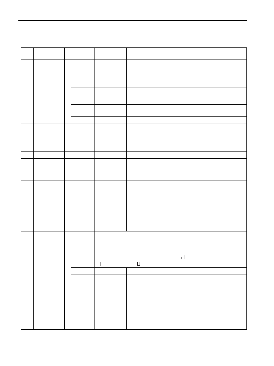
Table 5.7 Motion Monitoring Parameters (cont’d)
No.
Name
Register
Number
Setting Range/
Bit Name
Description