Yaskawa MP920 Motion Module User Manual
Page 355
7.3 PO-01 Parameters
7-53
7
35
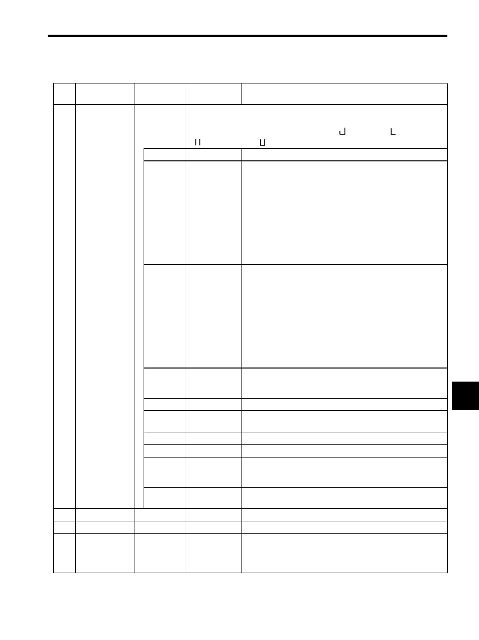
Alarms
(ALARM)
IL22
Alarm data and a halt to operation are indicated if this register shows anything other than
“0.” The register can be cleared by starting up OB006: Alarm Clear. If an alarm
occurs, the PO-01 Module indicators will indicate (
) (first axis), (
) (second axis),
(
) (third axis) and (
)(fourth axis). The bit configuration is described below.
Bits 0 to 2
Not used.
−
Bit 3
Positive
Software Limit
(SOTF)
This bit is valid if IB156: Zero Point Return Completed turns
ON when the positive software limit is enabled and an infinite length
axis is selected.
1. OW20: Motion Command Code Interpolation
This bit turns ON when IL18: Reference Position in
Machine Coordinate System + OL26: Stopping Distance
≥
Positive Software Limit (motion fixed parameter No. 27).
2. OW20: Motion Command Codes Positioning, Feed, or Step
This bit turns ON when IL18: Reference Position in
Machine Coordinate System
≥ Positive Software Limit (motion
fixed parameter No. 27).
Bit 4
Negative
Software Limit
(SOTR)
This bit is valid if IB156: Zero Point Return Completed turns
ON when the negative software limit is enabled and an infinite
length axis is selected.
1. OW20: Motion Command Code Interpolation
This bit turns ON when IL18: Reference Position in
Machine Coordinate System + OL26: Stopping Distance
≤
Negative Software Limit (motion fixed parameter No. 29).
2. OW20: Motion Command Codes Positioning, Feed, or Step
This bit turns ON when IL18: Reference Position in
Machine Coordinate System
≤ Negative Software Limit (motion
fixed parameter No. 29).
Bit 5
Excitation OFF
(SVOFF)
Turns ON if Motion Command Code (OW20) is set to a move-
ment command such as POSITIONING or STEP while the system is
in excitation OFF status.
Bit 6
Not used.
−
Bit 7
Overspeed
(DISTOVER)
Turns ON when an attempt is made to output the number of pulses
that exceeds the maximum pulse output frequency for each scan.
Bit 8
Not used.
−
Bit 9
Not used.
−
Bit 10
Control Mode
Error
(MODERR)
Turns ON when a move command is set at OW20: Motion Com-
mand Code in a mode other than Position Control Mode
(OB002 is OFF).
Bits 11 to
31
Not used.
−
37
Not used.
IW24
−
−
38
Not used.
IW25
−
−
39
Speed Refer-
ence Output
Monitor
(RVMON)
IL26
-2
31
to 2
31
-1
Indicates the travel distance every scan and is “0” when IB170:
Machine Locked is ON.
Table 7.11 Motion Monitoring Parameters (cont’d)
No. Name
Register
No.
Setting
Range/
Bit Name
Description