2 motion setting parameters – Yaskawa MP920 Motion Module User Manual
Page 130
4 Parameters
4.2.2 Motion Setting Parameters
4-10
4.2.2
Motion Setting Parameters
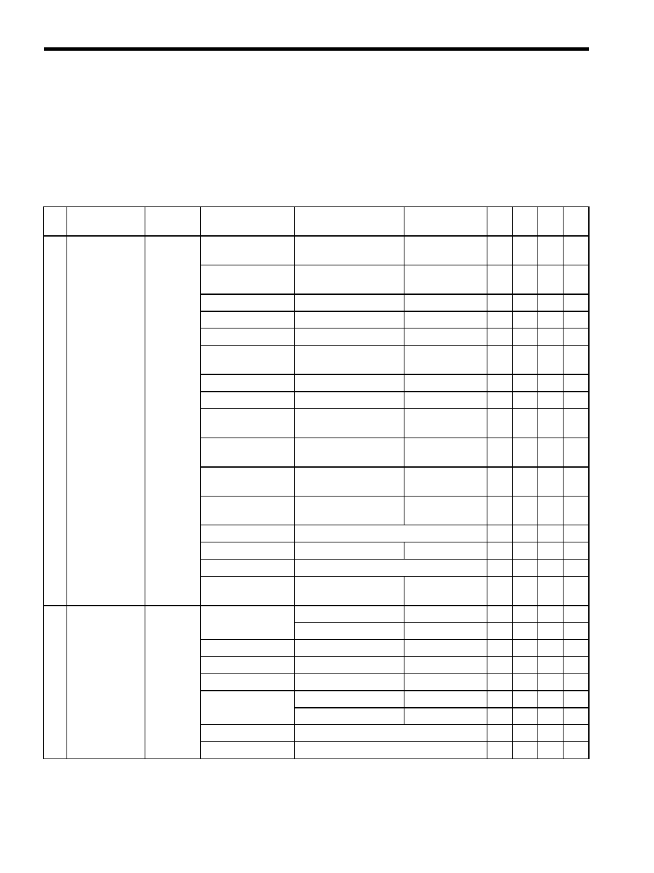
Motion setting parameters serve as instructions to Motion Modules. They are located at the
top of high-speed scans and are sent together to Motion Modules. Motion can be controlled
simply by setting parameters in these registers.
Table 4.3 Motion Setting Parameters
No.
Name
Register
Number
Setting Range/
Bit Name
Meaning
Remarks
SVA
-01A
SVA
-02
A
SVB
-01
PO-
01
1
RUN Mode
Settings
(RUNMODE)
OW00
Bit 0: NCON
Speed Reference Output
Mode
0: OFF, 1:ON
√
√
−
−
Bit 1: TCON
Torque Reference Output
Mode
0: OFF, 1:ON
−
√
−
−
Bit 2: PCON
Position Control Mode
0: OFF, 1:ON
√
√
√
√
Bit 3: PHCON
Phase Control Mode
0: OFF, 1:ON
√
√
−
−
Bit 4: ZRN
Zero Point Return Mode
0: OFF, 1:ON
√
√
−
−
Bit 5: PHTEST
Phase Control Test
Signal
0: OFF, 1:ON
√
√
−
−
Bit 6: ACR
Alarm Clear
0: OFF, 1:ON
√
√
√
√
Bit 7: PHREFOFF
Phase Reference Disable
0: OFF, 1:ON
√
√
−
−
Bit 8: MCDSEL
Motion Command Mode
Selection
0: OFF, 1:ON
√
√
√
√
Bit 9: ZRNDIR
Zero Point Return
Direction Selection
0: OFF, 1:ON
√
√
√
√
Bit 10: ABSRD
Absolute Position Read
Request
0: OFF, 1:ON
√
√
−
−
Bit 11
Feed Forward Gain at
Switching Control Mode
0: OFF, 1:ON
√
√
−
−
Bit 12
Not used.
−
−
−
−
Bit 13: DIINTREQ
DI Latch Request
0: OFF, 1:ON
√
√
−
−
Bit 14
Not used.
−
−
−
−
Bit 15: IRESET
Phase Control
Integration Reset
0: OFF, 1:ON
√
√
−
−
2
RUN Command
Settings
(SVRUNCMD)
OW01
Bit 0: RUN
Servo ON (DO0)
0: OFF, 1: ON
√
√
√
Excitation ON (DO0)
0: OFF, 1: ON
−
−
−
√
Bit 1: DO1
DO1
0: OFF, 1: ON
√
√
−
√
Bit 2: DO2
DO2
0: OFF, 1: ON
√
√
−
√
Bit 3: DO3
DO3
0: OFF, 1: ON
√
√
−
√
Bit 4: DO4
ROC
0: OFF, 1: ON
√
−
−
−
DO4
0: OFF, 1: ON
−
√
−
−
Bit 5
Not used.
−
−
−
−
Bits 6 to 10
Not used.
−
−
−
−