Yaskawa MP920 Motion Module User Manual
Page 195
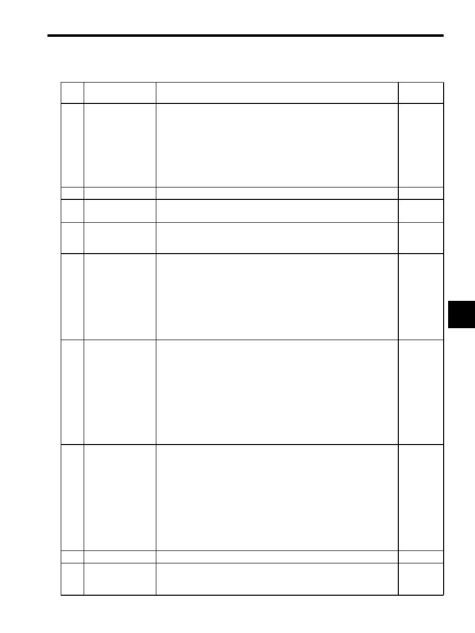
5.4 SVA-01A and SVA-02A Parameters
5-53
5
5
Pulse Counting
Mode Selection
(PULMODE)
Set the pulse counting method. Set one of the following seven modes to match the
pulse read method for the system that is used.
0: Sign,
×1
1: Sign,
×2
2: Up/Down,
×1
3: Up/Down,
×2
4: A/B pulses,
×1
5: A/B pulses,
×2
6: A/B pulses,
×4
6
(A/B pulses
× 4)
6
Not used.
−
−
7
Rated Motor Speed
Setting (NR)
Set motor speed at rated (100%) operation in 1 min
-1
units. Set this parameter
based on the specifications of the Servomotor that is used.
3000
8
Number of Feedback
Pulses per Rotation
(FBppr)
Set the number of feedback pulses per Servomotor rotation (no multiplier). Set
this parameter based on the specifications of the encoder that is used.
• Setting range: Set a multiple of 4 between 4 and 65532 (p/r).
2048
9
D/A Output Voltage
at 100% Speed (V1)
Set the D/A output voltage when the speed reference is set to 100%. Normally set
the rated rotation input voltage of the servo drive. Set this parameter based on the
specifications of the servo drive that is used.
• Setting range: 0.001 to 10.000 (V)
• D/A output = (OW15: Speed Reference Setting
× D/A Output Voltage at
100% Speed (fixed parameter 9) / 10000
Example: D/A output voltage setting at 100% speed = 6 V
If the speed reference value = 100%, then (10000
×6 V) / 10000 = 6.0 V
is output.
6.000
10
D/A Output Voltage
at 100%
Torque Limit (V2)
Set the D/A output voltage when the torque limit reference is set to 100%. The
voltage is the same on the positive and negative sides. Normally set the current
limit when using a SERVOPACK and the torque limit when using a VS-866. Set
this parameter based on the specifications of the servo drive that is used.
• Setting range: 0.001 to 10.000 (V)
• D/A output = (OW02: Positive Torque Limit Setting
× D/A Output Voltage
at 100% Torque Limit (fixed parameter 10)) / 10000
Example: D/A Output Voltage at 100% Torque Limit = 3 V
If the Positive Torque Limit Setting = 200%, then (20000
× 3 V) /
10000 = 6.0 V is output.
Note: Valid only for SVA-02A (2-axis) Module.
3 V
(= 3.000)
11
Input Voltage at
100% Speed
Monitoring
(A/D) (MV1)
Set scaling in 1 mV units in order to convert the voltage input from the A/D con-
verter to a speed monitor value (%).
• Setting range: 0.001 to 10.000 (V)
The speed monitor value is calculated using the following equation and is indi-
cated at IW0D: Speed Monitor.
• Speed monitor value = (A/D input voltage
× 10000) / Input Voltage at 100%
Speed Monitoring (A/D)
Example: Input voltage setting at 100% speed monitoring (A/D) = 6 V
If the actual A/D input voltage = 3 V, then (3 V
× 10000) / 6.0 V = 5000
is indicated at IW0D.
Note: Valid only for SVA-02A (2-axis) Module.
6.000
12
Not used.
−
−
13
DI Latch Signal
Selection
(DIINTSEL)
Set the external signal that is used to latch DI.
0: Use the DI signal as a latch signal.
1: Use the Pulse C as the latch signal.
0
Table 5.5 Motion Fixed Parameters (cont’d)
No.
Name
Description
Factory
Setting