2 sva-02a module, 1 hardware specifications – Yaskawa MP920 Motion Module User Manual
Page 166
5 SVA Module Specifications and Handling
5.2.1 Hardware Specifications
5-24
5.2
SVA-02A Module
This section describes the specifications and handling of the SVA-02A (2-axis) Module.
5.2.1
Hardware Specifications
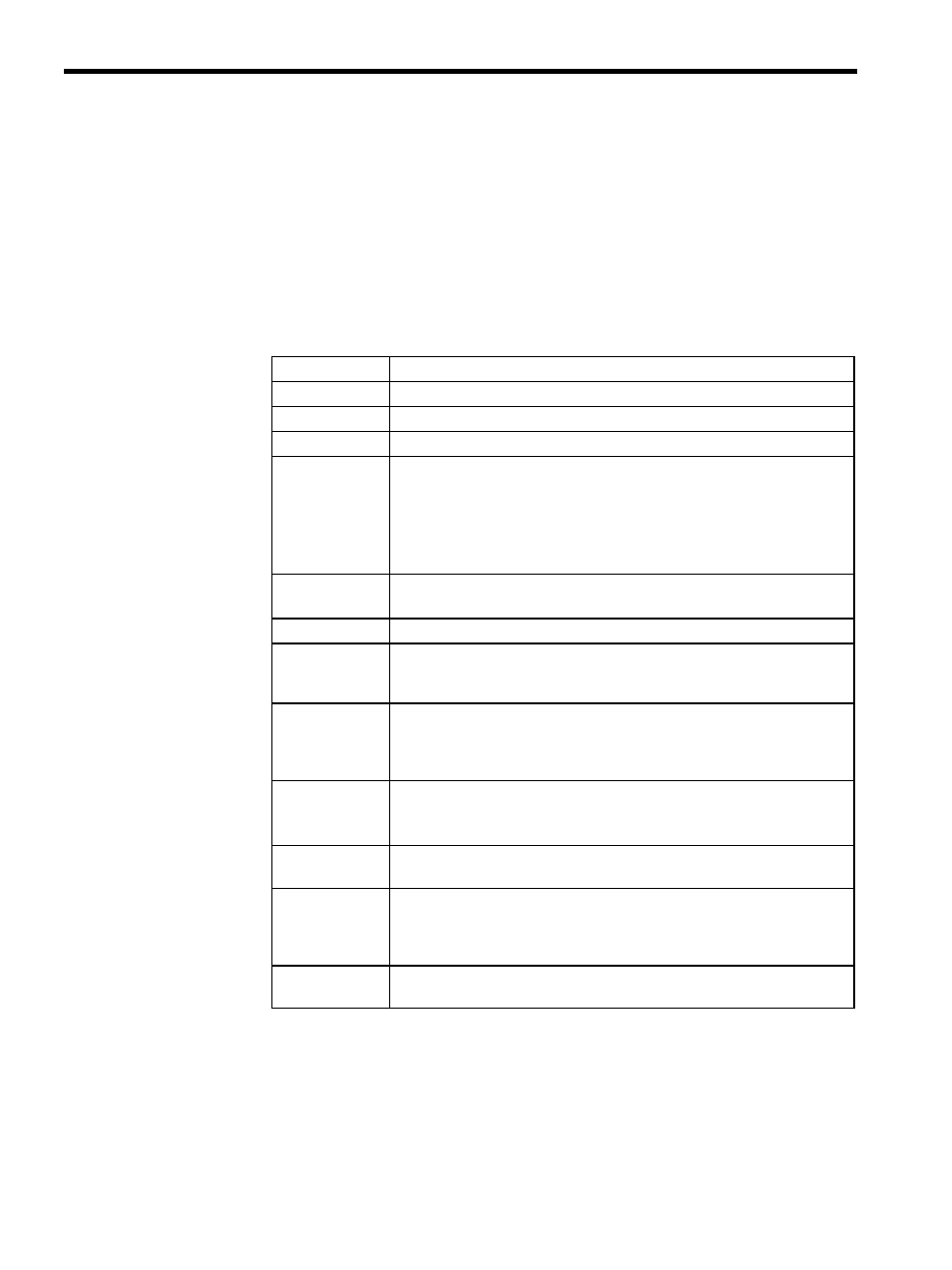
Table 5.3 shows the SVA-02A Module hardware specifications.
Table 5.3 SVA-02A Module Hardware Specifications
Item
Specifications
Name
Two-axis Servo Module
Model Number
JEPMC-MC220A
Description
SVA-02A
Servo Interface
Pulse input circuit: 5 V differential, maximum 1 MHz input
(Maximum 1.5 MHz input for the hardware Ver. B.5 or
later.)
Pulse input method: A/B/C phase input (selected from 1
×, 2×, and 4×), A/B
mode, sign mode, up-down mode
Pulse counter latch: DI
Analog Outputs
D/A speed references: PWM 16 bits 2 channels
Torque references:
D/A 12 bits 2 channels
Analog Inputs
16 bits
× 2 channels
Digital Inputs
General-purpose DI: 6 points
× 2 channels, 4 mA at 24 VDC, source input
General-purpose DI (RDY, ALM, BRK, OTF, OTR)
PI latch
Digital Outputs
General-purpose DO: 6 points
× 2 channels, 24 VDC ±2%
Output current: 100 mA
SV ON, ALM RST, P_CON, SEN, General 1, General 2
(SEN output is 5 V source and 24 V output.)
Connectors
CN1: Servo connector 1 10236-52A2JL
CN2: Servo connector 2 10236-52A2JL
CN3: 24 V input
BL3.5/2F-AU
Indicators
Module status LED indicator
7-segment LED (green)
Hot Swapping
(Removal/Inser-
tion under Pow-
er)
Not possible
Dimensions
(mm)
40
× 130 × 105 mm (W × H × D)