2 handling – Yaskawa MP920 Motion Module User Manual
Page 145
5.1 SVA-01A Module
5-3
5
* The SVA-01A Module does not support brake control and does not have
the registers for brake control (OW). The brake control output
signals from CN5 merely pass the brake ON input signal for each axis
from CN1 to CN4 without altering them. (Refer to
5.3.5 Connection
with SGDA-
S SERVOPACK
.)
With Yaskawa servo systems, the SERVOPACK controls braking. The
brake control output signals are thus passed through the SVA-01A Mod-
ule and output as the brake control output signals from CN5. When using
a servo drive from another company that does not control braking, pre-
pare separate brake control I/O and program brake controls in the ladder
diagram.
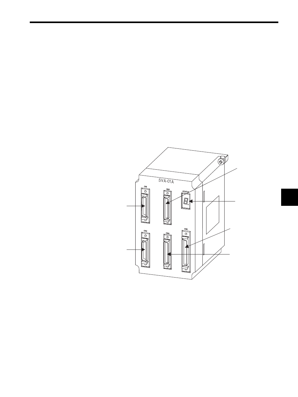
5.1.2
Handling
The following illustration shows the appearance of the SVA-01A Module.
Servo connector
CN1
Servo connector
CN3
Servo connector
CN4
External interface
connector CN5
LED indicator
Servo connector
CN2