Po-01 module connection example – Yaskawa MP920 Motion Module User Manual
Page 316
Advertising
7 PO-01 Module Specification and Handling
7.1.2 Handling
7-14
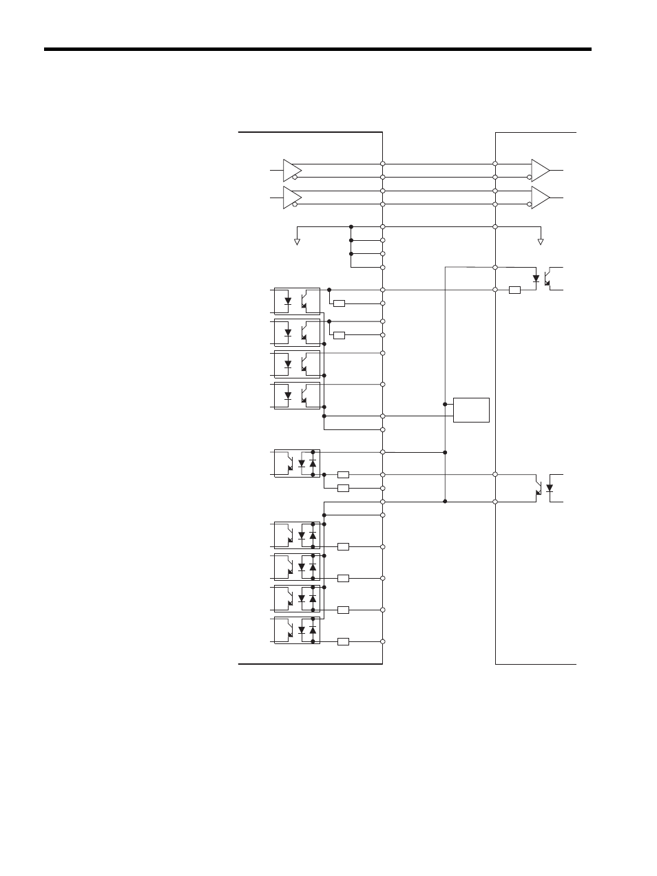
PO-01 Module Connection Example
Note: The pulse input and the digital input/output have two channels for
one connector. The channels for the terminal numbers () is
as follows:
• : channel 1
• (): channel 2
DI_1
CW+
CW-
CCW+
CCW-
4
GND
29
15
40
DO_0
DO_1
DO_2
DO_3
24
49
23
48
DI_0
DI_0+
DI_0- (24V)
DI_0- (5/12V)
24V
DI_2
DI_3
DI_4
CW
CCW
PO-01
Pulse amplifier
2 (13)
3 (14)
27 (38)
28 (39)
31 (42)
32 (43)
33 (44)
34 (45)
35 (46)
36 (47)
8 (19)
5 (16)
6 (17)
7 (18)
9 (20)
10 (21)
11 (22)
Pulse input
CN1 or CN2
CW+
CW-
CCW+
CCW-
DO_0
DO_0 (R)
DO_1
DO_1 (R)
DO_2
DO_3
0V
0V
Digital output
+24V
0
24
V
24V
DI_1
DI_2
DI_3
DI_4
Digital output
Advertising
See also other documents in the category Yaskawa Equipment:
- Tag Generator (30 pages)
- MP3300iec (82 pages)
- 1000 Hz High Frequency (18 pages)
- 1000 Series (7 pages)
- PS-A10LB (39 pages)
- iQpump Micro User Manual (300 pages)
- 1000 Series Drive Option - Digital Input (30 pages)
- 1000 Series Drive Option - CANopen (39 pages)
- 1000 Series Drive Option - Analog Monitor (27 pages)
- 1000 Series Drive Option - CANopen Technical Manual (37 pages)
- 1000 Series Drive Option - CC-Link (38 pages)
- 1000 Series Drive Option - CC-Link Technical Manual (36 pages)
- 1000 Series Drive Option - DeviceNet (37 pages)
- 1000 Series Drive Option - DeviceNet Technical Manual (81 pages)
- 1000 Series Drive Option - MECHATROLINK-II (32 pages)
- 1000 Series Drive Option - Digital Output (31 pages)
- 1000 Series Drive Option - MECHATROLINK-II Technical Manual (41 pages)
- 1000 Series Drive Option - Profibus-DP (35 pages)
- AC Drive 1000-Series Option PG-RT3 Motor (36 pages)
- Z1000U HVAC MATRIX Drive Quick Start (378 pages)
- 1000 Series Operator Mounting Kit NEMA Type 4X (20 pages)
- 1000 Series Drive Option - Profibus-DP Technical Manual (44 pages)
- CopyUnitManager (38 pages)
- 1000 Series Option - JVOP-182 Remote LED (58 pages)
- 1000 Series Option - PG-X3 Line Driver (31 pages)
- SI-EN3 Technical Manual (68 pages)
- JVOP-181 (22 pages)
- JVOP-181 USB Copy Unit (2 pages)
- SI-EN3 (54 pages)
- SI-ET3 (49 pages)
- MECHATROLINK-III (35 pages)
- EtherNet/IP (50 pages)
- SI-EM3 (51 pages)
- 1000-Series Option PG-E3 Motor Encoder Feedback (33 pages)
- 1000-Series Option SI-EP3 PROFINET (56 pages)
- PROFINET (62 pages)
- AC Drive 1000-Series Option PG-RT3 Motor (45 pages)
- SI-EP3 PROFINET Technical Manual (53 pages)
- A1000 Drive Option - BACnet MS/TP (48 pages)
- 120 Series I/O Modules (308 pages)
- A1000 12-Pulse (92 pages)
- A1000 Drive Software Technical Manual (16 pages)
- A1000 Quick Start (2 pages)
- JUNMA Series AC SERVOMOTOR (1 page)
- A1000 Option DI-101 120 Vac Digital Input Option (24 pages)