Yaskawa MP920 Motion Module User Manual
Page 127
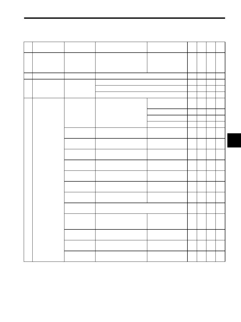
4.2 Parameter List by Module
4-7
4
14
Additional Func-
tion Selections
(AFUNCSEL)
(cont’d)
Bit 9
Selection for Feedback Pulses
per Motor Rotation for High-res-
olution
0: Disabled
1: Enabled
−
−
√
−
15
Not used.
−
−
−
−
−
−
16
Simulation Mode
Selection
0 to 2
(Default = 0)
0: Normal operation mode
√
√
√
−
1: Simulation mode
√
√
√
−
2: Factory Adjustment Mode
√
√
−
−
17
Motion Controller
Function Selection
Flags
(SVFUNCSEL)
Bits 0 to 3: 0 to 7
CMD_UNIT
Reference Unit Selection
0: pulse (Electronic gear
disabled)
√
√
√
√
1: mm
√
√
√
√
2: deg
√
√
√
√
3: inch
√
√
√
√
Bit 4:
USE_GEAR
Electronic Gear Selection
0: Disabled
1: Enabled
√
√
√
√
Bit 5:
PMOD_SEL
Axis Selection
0: Finite length axis
1: Infinite length axis
√
√
√
√
Bit 6:
USE_BKRSH
Backlash Compensation Enabled
Selection
0: Disabled
1: Enabled
√
√
−
−
Bit 7:
USE_SLIMP
Positive Software Limit
Selection
0: Disabled
1: Enabled
√
√
√
√
Bit 8:
USE_SLIMN
Negative Software Limit
Selection
0: Disabled
1: Enabled
√
√
√
√
Bit 9:
USE_OV
Override Selection
0: Disabled
1: Enabled
√
√
√
√
Bit 10:
INV_DEC
Deceleration Limit Switch
Inversion Selection
0: Do not reverse.
1: Reverse.
√
√
−
√
Bit 11:
Not used.
−
−
−
−
−
Bit 12
Servo Driver Transparent
Command Mode
0: Normal
1: Transparent
command mode
−
−
√
−
Bit 13:
OVT1_SEL
Positive Overtravel Selection
0: Disabled
1: Enabled
√
√
−
−
Bit 14:
OVT2_SEL
Negative Overtravel Selection
0: Disabled
1: Enabled
√
√
−
−
Bit 15:
SEGBUF
Interpolation Segment Distribu-
tion Processing Selection
0: Disabled
1: Enabled
−
−
√
−
Table 4.2 Motion Fixed Parameters (cont’d)
No.
Name
Setting Range/
Bit Name
Meaning
Remarks
SVA
-01A
SVA
-02
A
SVB
-01
PO-
01