3 processing after an alarm, Alarm data, Clearing a software limit alarm – Yaskawa MP920 Motion Module User Manual
Page 397

9.3 Software Limit Function
9-17
9
The following table shows the effect of software limits in each operating mode.
The software limit function will be enabled after returning to the zero point in Position Control Mode
or after the zero point is set.
9.3.3
Processing after an Alarm
Alarm Data
A forward/reverse direction software limit alarm will occur if an axis exceeds the software
limit. This alarm can be monitored from the monitoring parameter alarm (IL22).
Clearing a Software Limit Alarm
The following procedure is used to clear alarm status generated by a software limit alarm.
1. Alarm Reset
Turn ON Alarm Clear (bit 6) of RUN Mode Settings (OW00).
The alarm at IL22 will be cleared.
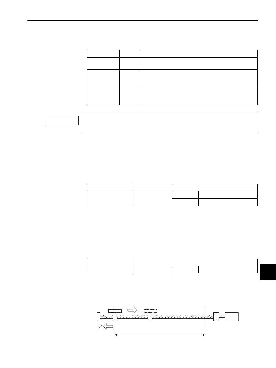
2. Return
The FEED and STEP commands can be used to move the machine back inside the soft-
ware limit.
Axis Movement
Check
Remarks
Interpolation
Yes
• Constantly checks the software limit range during interpolation
movement and decelerates to a stop at the software limit position.
Feed
Yes
• Executes a command to move to the software limit position when
the software limit function is enabled.
• Can move back to within the stroke after an error is cleared.
Positioning
Step
Yes
• Positions the axis at the upper software limit and generates an
alarm if a positioning command is executed to move to a position
beyond the software limits.
IMPORTANT
Name
Register No.
Meaning
Alarms (ALARM)
IL22
Bit 3: SOTF
Positive software limit
Bit 4: SOTR
Negative software limit
Name
Register Setting
Meaning
RUN Mode Settings
OW00
Bit 6: ACR
Alarm clear
Return command received.
Another alarm will occur if the machine is
instructed to return to the software limit.
Software limit
(lower limit)
Software limit
(upper limit)
Servo-
motor