User program example example of run operation, Operating conditions, Ladder logic program example – Yaskawa MP920 Motion Module User Manual
Page 51
2.2 Control Modes
2-25
2
User Program Example
Example of RUN Operation
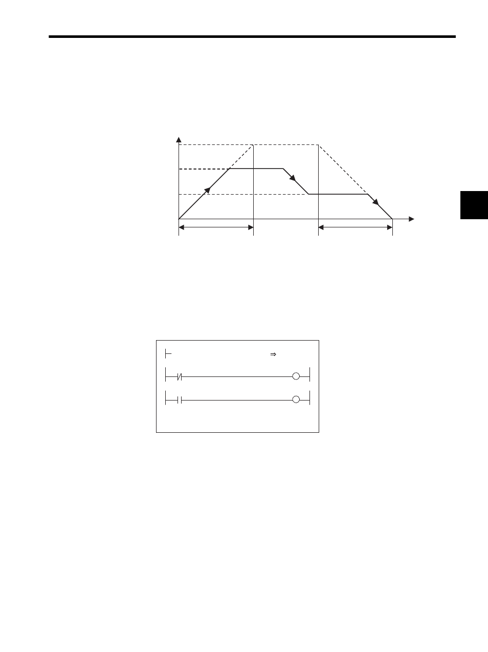
Fig. 2.11 Zero Point Return Pattern
Operating Conditions
Input a limit switch signal width at least twice that of the high-speed scan setting.
Ladder Logic Program Example
Fig. 2.12 RUN Commands (DWG H01)
The example in the above illustration has been greatly simplified. In actual operation, each
register can be controlled from the user program.
0
NACC
NDEC
Time (t)
Napr
Nclp
Approach speed
Creep speed
Speed
(%)
NR
(100%)
H0110
RUNMOD
OWC0C0
Set the zero point return mode to ON.
IB00100: Limit switch signal (DECLS)
Driver RUN command (RUN)
When IB00110 turns ON, the zero point
return operation starts. When the zero
point return operation is completed, the
zero point return completion signal
IBC0C0F (ZRNC) turns ON.
LSDEC
OBC0C1F
IB00100
RUN
OBC0C10
RUNPB
IB00110
DEND