Yaskawa MP920 Motion Module User Manual
Page 276
6.2 SVB-01 Parameters
6-41
6
24
Position
Control Status
(POSSTS)
(cont’d)
Bits 12 to
15
Servo Driver
User Monitor
Information
Selection
Response (USR-
MONSELR)
Contain the type of monitor information that is applicable to the value
stored in IL20 (Servo Drive User Monitor Information).
0 to F
25
Machine Coor-
dinate System
Reference Po-
sition (MPOS)
IL18
-2
31
to 2
31
-1
This parameter is the reference position in the machine coordinate sys-
tem and is basically the same value at IL02 (CPOS). This position
data cannot be refreshed if IB170: Machine Lock ON.
27
Not used.
IL1A
−
−
29
POSMAX
Monitor
(PMAXTURN)
IL1C
1 to 2
31
-1
Indicates the infinite length axis reset position (POSMAX) at motion
fixed parameter No. 23.
31
Number of
POSMAX
Turns
(PMAXTURN)
IL1E
-2
31
to 2
31
-1
The count at this parameter goes up and down every time the reset
position (POSMAX) for the infinite length axis at motion fixed
parameter 23 is exceeded. The parameter can be preset with
OL30: Preset Number of POSMAX Turns and with OB2D1:
Request for Preset Number of POSMAX Turns.
33
Servo Driver
User Monitor
Information
(USRMON)
IL20
-2
31
to 2
31
-1
Indicates the MECHATROLINK servo monitor information specified
in bits 12 to 15 of OW2D.
35
Alarms
(ALARM)
IL22
This parameter is valid in Position Control Mode when an OW20: Motion Command
Code is used. Alarm data and a halt to operation are indicated if this register shows any-
thing other than “0.” The register can be cleared by starting up OB006: Alarm Clear.
If an alarm occurs, the SVB Modules indicators will indicate (
) . The bit configuration
is described below.
Bit 0
SERVOPACK
Error
(SVERROR)
Turns ON when a SERVOPACK alarm is detected.
For alarm details, refer to IW24.
Bit 1
Positive
Overtravel
(OTF)
Turns ON when the positive overtravel signal is input and a move
command is executed in the positive direction.
Bit 2
Negative
Overtravel
(OTR)
Turns ON when the negative overtravel signal is input and a move
command is executed in the negative direction.
Bit 3
Positive
Software Limit
(SOTF)
Valid if IB156: Zero Point Return Completed turns ON when the
positive software limit is enabled and an infinite length axis is
selected.
OW20: Motion Command Code Interpolation
This bit turns ON when IL18: Reference Position in Machine
Coordinate System + OL26: Stopping Distance
≥ Positive
Software Limit (motion fixed parameter No. 27).
OW20: Motion Command Codes Positioning, Feed, or Step
This bit turns ON when IL18: Reference Position in Machine
Coordinate System
≥ Positive Software Limit (motion fixed param-
eter no. 27).
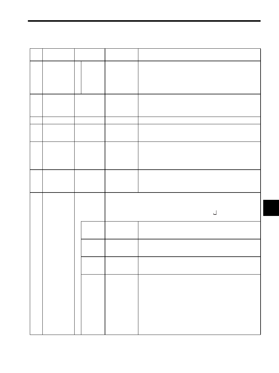
Table 6.4 Motion Monitoring Parameters (cont’d)
No.
Name
Register
Number
Setting Range/
Bit Name
Description