Yaskawa MP920 Motion Module User Manual
Page 133
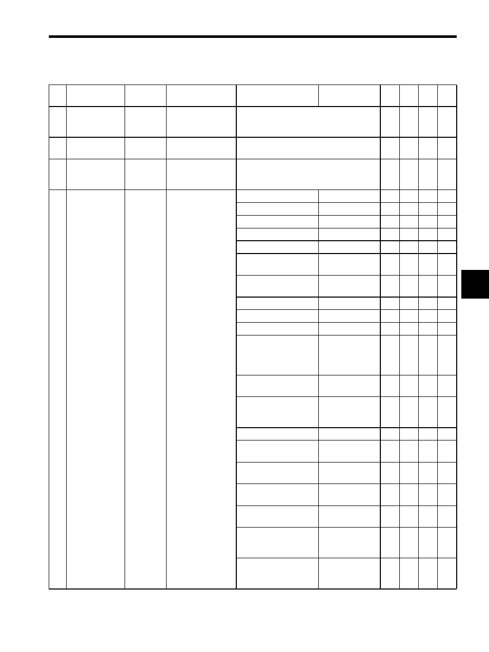
4.2 Parameter List by Module
4-13
4
29
Speed Limit
Setting
(NLIM)
OW1C -32768 to 32767
(Default = 15000)
1 = 0.01%
(15000 = 150.00%)
−
√
−
−
30
Speed Loop Gain
(kv)
OW1D 1 to 20000
Set to “0.”
−
−
√
−
31
Pulse Bias
Setting
(PULBIAS)
OL1E
-2
31
to 2
31
-1
(Default = 0)
1 = 0.1 Hz
√
√
−
√
33
Motion
Command Code
(MCMDCODE)
OW20
0 to 65535
(Default = 0)
0: NOP
No operation
√
√
√
√
1: POSING
Positioning
√
√
√
√
2: EX_POSING
External position
√
√
√
−
3: ZRET
Zero point return
√
√
√
√
4: INTERPOLATE
Interpolation
√
√
√
√
5: ENDOF_
INTERPOLATE
Interpolation end
segment
√
√
√
√
6: LATCH
Interpolation with
latch
√
√
√
−
7: FEED
Feed
√
√
√
√
8: STEP
Step
√
√
√
√
9: ZSET
Zero point setting
√
√
√
√
10: ACC
Change 1-step lin-
ear acceleration/
deceleration time
constant
−
−
√
−
11: DCC
Change decelera-
tion time constant
−
−
√∗
−
12: SCC
Change moving
average time con-
stant
−
−
√
−
13: CHG_FILTER
Change filter type
−
−
√
−
14: KVS
Change speed
loop gain (Kv)
−
−
√
−
15: KPS
Change position
loop gain (Kp)
−
−
√
−
16: KFS
Change feed
forward (Kf)
−
−
√
−
17: CN_RD
Read servo driver
Cn constants
−
−
√
−
18: CN_WR
Change servo
driver Cn
constants
−
−
√
−
19: ALM_MON
Monitor current
servo driver
alarms
−
−
√
−
Table 4.3 Motion Setting Parameters (cont’d)
No.
Name
Register
Number
Setting Range/
Bit Name
Meaning
Remarks
SVA
-01A
SVA
-02
A
SVB
-01
PO-
01