Yaskawa MP920 Motion Module User Manual
Page 227
5.4 SVA-01A and SVA-02A Parameters
5-85
5
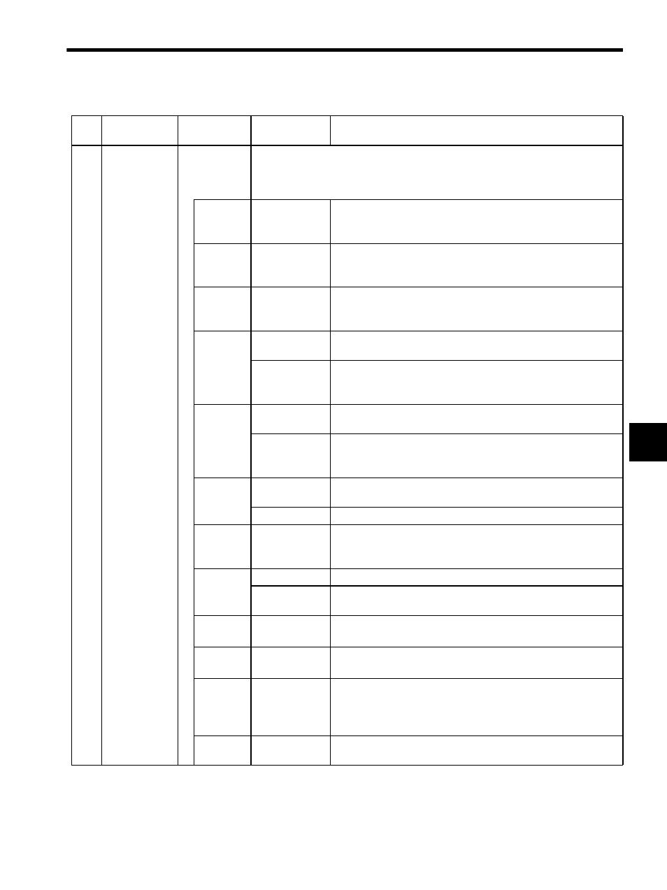
2
General-pur-
pose DI
Monitor
(SVSTS)
IW01
Monitors the status of input signals or general-purpose DI signals from the SERVOPACK.
None of these signals are used for control in the Motion Module.
Use this parameter for control in user programs as needed. The bit configuration is
described below.
Bit 0
General-purpose
DI (DI0)
(SVALM)
Indicates DI0 signal status.
See 1 of Supplemental Explanation 4.
Bit 1
General-purpose
DI (DI1)
(SRDY)
Indicates DI1 signal status.
See 1 of Supplemental Explanation 4.
Bit 2
General-purpose
DI (DI2)
(BRK)
Indicates DI2 signal status.
See 1 of Supplemental Explanation 4.
Bit 3
Broken PG Wire
Indicates broken PG wire status (0 if the wire is broken) in SVA-01A
(4-axis) Module.
DI3 (OTF)
Indicates the status of DI3 signal in SVA-02A (2-axis) Module. It con-
nects to DI3 when positive overtravel signals are used.
See 1 of Supplemental Explanation 4.
Bit 4
DI3 (OTF)
Indicates positive overtravel signal status in SVA-01A (4-axis) Mod-
ule.
DI4 (OTR)
Indicates DI4 signal status in SVA-02A (2-axis) Module. It connects
to DI4 when negative overtravel signals are used.
See 1 of Supplemental Explanation 4.
Bit 5
DI4 (OTR)
Indicates negative overtravel signal status in SVA-01A (4-axis) Mod-
ule.
DI5 (EXT)
Indicates external latch signal status in SVA-02A (2-axis) Module.
Bit 6
DI5 (DEC)
Indicates DI5 signal status in SVA-01A (4-axis) Module. It connects
to DI5 when a deceleration limit switch signal is used.
Note: It is not valid for SVA-02A (2-axis) Module.
Bit 7
DI6 (ZERO)
Indicates ZERO signal status in SVA-01A (4-axis) Module.
Broken PG Wire Indicates broken PG wire status (0 if the wire is broken) in SVA-02A
(2-axis) Module.
Bit 8
DI7 (EXT)
Indicates external latch signal status in SVA-01A (4-axis) Module.
Note: It is not valid for SVA-02A (2-axis) Module.
Bit 9
DI8 (RIn)
Indicates DI8 signal status in SVA-01A (4-axis) Module.
Note: It is not valid for SVA-02A (2-axis) Module.
Bit 10
DI9 (RIC)
Indicates DI9 signal status on the first axis with SVA-01A (4-axis)
Module.
Note: It is not valid on the second to the fourth axis of SVA-01A
(4-axis) Module or for SVA-02A (2-axis) Module.
Bits 11 to
15
Not used.
−
Table 5.7 Motion Monitoring Parameters (cont’d)
No.
Name
Register
Number
Setting Range/
Bit Name
Description