Dec1 + phase-c pulse – Yaskawa MP920 Motion Module User Manual
Page 83
2.4 Position Control Using Motion Commands
2-57
2
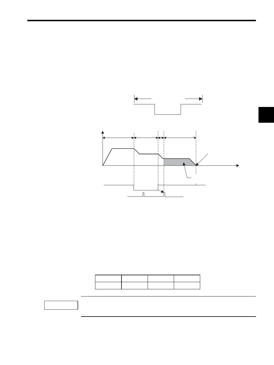
DEC1 + Phase-C Pulse
This method is used to perform zero point return using a limit switch (deceleration limit
switch) and a zero point signal (Phase-C pulse) by rapid traverse using linear acceleration/
deceleration (with a dog width).
The limit switch is used with a mechanical configuration such as the one shown in the fol-
lowing illustration.
1. The axis travels at rapid traverse speed in the direction specified in the motion setting
parameter (OB009).
2. The axis decelerates to approach speed at the falling edge of the dog (deceleration limit
switch) signal.
3. The axis decelerates to creep speed at the rising edge of the dog (deceleration limit
switch) signal.
4. When the dog goes high, the axis stops after traveling only the zero point return final
travel distance (OL2A) from the initial zero point signal (Phase-C pulse), and that
position will be the machine coordinate system zero point.
Automatic return is not performed with this zero point return method. Where zero point return to a
position is not possible, use a manual operation to return to the zero point.
SVA-01A
SVA-02A
SVB-01
PO-01
Available
Available
Available
Not available
High
Low
Deceleration limit switch
Machine total
operating area
0
1.
2.
3.
4.
Reverse direction
← → Forward direction
Speed
reference
Dog
(Deceleration limit switch)
Zero point signal
(Phase-C pulse)
Rapid traverse
speed
Approach
speed
Creep speed
Zero point return
position
Zero point
Time
Zero point return final
travel distance
IMPORTANT