1 po-01 module, 1 hardware specifications – Yaskawa MP920 Motion Module User Manual
Page 304
7 PO-01 Module Specification and Handling
7.1.1 Hardware Specifications
7-2
7.1
PO-01 Module
This section describes the hardware specifications and handling of the PO-01 Module.
7.1.1
Hardware Specifications
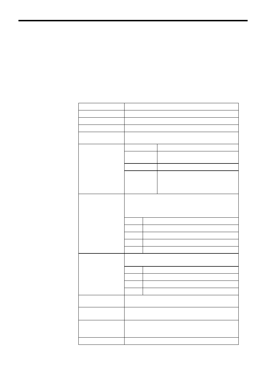
The following table shows the PO-01 hardware specifications.
Table 7.1 PO-01 Module Hardware Specifications
Item
Specifications
Name
Pulse Output Module
Model Number
JEPMC-PL210
Description
PO-01
Number of Controlled
Axes
4
Pulse Outputs
Method
Sign + pulse, pulse
Maximum
Frequency
500 kpps (switched using software)
Interface
5-V differential output
Other Functions
Positive and negative logic switchable with
software.
Two emergency stop modes are supported
(immediate stop and deceleration to a stop).
Digital Inputs
Photocoupler isolation, current source input, 5 points
× 4 channels
DI_0: Separate for each power supply
5 V/5 mA, 12 V/12 mA, or 24 V/5 mA
DI_1 to DI_4: Common power source, 0.5-ms filter, 24 V/5 mA
Application
Examples
DI_0
Zero point
DI_1
Dog signal/general-purpose
DI_2
Limit 1
DI_3
Limit 2
DI_4
Emergency stop/deceleration to a stop
Digital Outputs
24 V open collector (current sink type), 4 points
× 4 channels
Photocoupler isolation, 100 mA max.
Application
Examples
DO_0
Excitation ON
DO_1
General-purpose output
DO_2
General-purpose output
DO_3
General-purpose output
Indicator
Module status LED
7-segment LED (green)
Connectors
CN1: 1- or 2-axis connector 10250-52A2JL
CN2: 3- or 4-axis connector 10250-52A2JL
Hot Swapping
(Removal/Insertion
under Power)
Not possible.
Dimensions
40
× 130 × 105 mm (W × H × D)