Coincidence output and interrupt functions, Important – Yaskawa MP920 Motion Module User Manual
Page 429
10 CNTR-01 Module Specifications and Handling
10.3.3 Frequency Measurement
10-28
Coincidence Output and Interrupt Functions
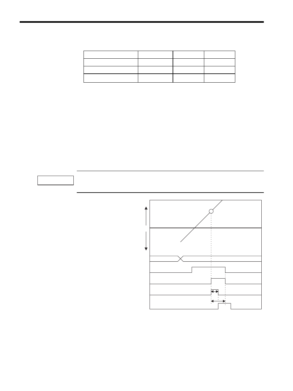
The Coincidence Output and Coincidence Interrupt Functions output an external signal
(coincidence detection signal) and an interrupt signal to the CPU Module when a preset out-
put register setting (coincidence detection setting: OL + 4) and the current counter
value are the same.
The Coincidence Output Function is enabled when fixed parameter 08 (Coincident Detec-
tion) is set to “Used.”
The Coincidence Interrupt Function is enabled when fixed parameter 09 (Coincident IRQ) is
set to “Used.”
The Coincidence Output and Coincidence Interrupt functions can be used in Reversible Counter, Inter-
val Counter, and Frequency Measurement modes.
* 1. Coincidence point detection value=Coincidence detection setting
(
IL+4
)
* 2. Coincidence detection request = Operating mode (
OL Bit 3
)
* 3. T0: The maximum time period from when the CPU Module has
received an interrupt signal until the interrupt processing is started (70
to 120
μ
s.)
* 4. T1: The time from when the interrupt request signal is received until
the execution of DWG.I (interrupt drawing) is started.
For normal program execution: Approx. 90 to 170
μ
s.
For direct I/O instruction execution: Approx. 90 to (1460 + 40 + n)
μ
s
N: No. of direct I/O words, 8 max.
Table 10.9 Output Data
Name
Register No.
Range
Meaning
Operating Mode
OW
Each bit
−
Set Average Number
OL + 1
0 to
± 255
1 = 1 pulse
Set Coincident Detection
OL + 4
0 to
± 2
31
-1
1 = 1 pulse
IMPORTANT
COINDAT
COINDAT
T0
*3
T1
*4
0
(+)
(-)
Coincidence point detection value
*1
Count register
Coincidence detection request
*2
Coincidence output signal
Interrupt request signal
Interrupt received