Supplemental explanation 4 – Yaskawa MP920 Motion Module User Manual
Page 228

5 SVA Module Specifications and Handling
5.4.3 Motion Monitoring Parameters
5-86
Supplemental Explanation 4
1. The following example shows when these parameters are used for servo drive status.
They are general-purpose DIs, and they can also be used in other applications.
* Logical value, i.e., OFF when the operation is executed.
* Logical value, i.e., OFF when the operation is executed.
2. When bit 7 (motion command code selection) of fixed parameter No. 14 is set to 1
(“Used”) and Motion Command Code Enable/Disable (OB
008) is set to 1 (“Valid”),
indicates the number of reference units. Otherwise, indicates the number of pulses.
3. The DI latch mode latches the current position in storage registers on the rising edge of
an external signal. Either a special discrete input signal called the DI input or the pulse
C input can be selected as the latch signal. The latch signal is selected in fixed parameter
13: DI Latch Detection.
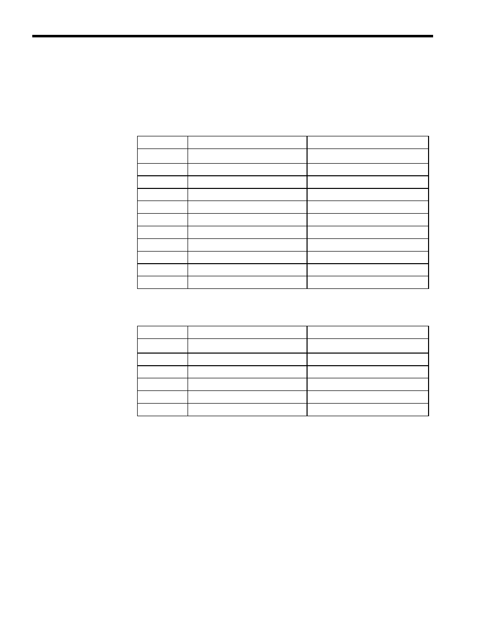
Table 5.8 SVA-01A (4-axis) Module
Name
Connected to a VS-866
Connected to a SERVOPACK
Bit 0 (DI0)
Alarm (ALM)
Servo alarm (ALM)
*
Bit 1 (DI1)
Preparations completed (RDYX)
Servo ready (S-RDY)
Bit 2 (DI2)
Operating (RUNX)
Brake input (BRK)
Bit 3
Not used.
Broken PG wire
Bit 4 (DI3)
Positive overtravel signal
Positive overtravel signal (OTF)
Bit 5 (DI4)
Negative overtravel signal
Negative overtravel signal (OTR)
Bit 6 (DI5)
Deceleration limit switch signal
Deceleration limit switch signal (DEC)
Bit 7 (DI6)
ZERO signal
ZERO signal
Bit 8 (DI7)
External latch signal
External latch signal (EXT)
Bit 9 (DI8)
Reserved.
Reserved. RIn
Bit 10 (DI9)
Reserved.
Reserved. RIC (only for one axis)
Table 5.9 SVA-02A (2-axis) Module
Name
Connected to a VSñ866
Connected to a SERVOPACK
Bit 0 (DI0)
Alarm (ALM)
Servo alarm (ALM)
*
Bit 1 (DI1)
Preparations completed (RDYX)
Servo ready (S-RDY)
Bit 2 (DI2)
Operating (RUNX)
Brake input (BRK)
Bit 3 (DI3)
Positive overtravel signal
Positive overtravel signal (OTF)
Bit 4 (DI4)
Negative overtravel signal
Negative overtravel signal (OTR)
Bit 5 (DI5)
External latch signal
External latch signal (EXT)