2 settings according to host controller, 1 speed reference, 2 settings according to host controller - 14 – Yaskawa Sigma II Series Servo System User Manual
Page 100: 1 speed reference - 14, 2 settings according to host controller -14, Speed reference -14, Setting examples
Sigma II User’s Manual
Chapter 5: Parameter Settings and Functions
5 - 14
5.2 Settings According to Host Controller
This section describes the procedure for connecting a Sigma II Series servo to a host
controller, including the procedure for setting related parameters.
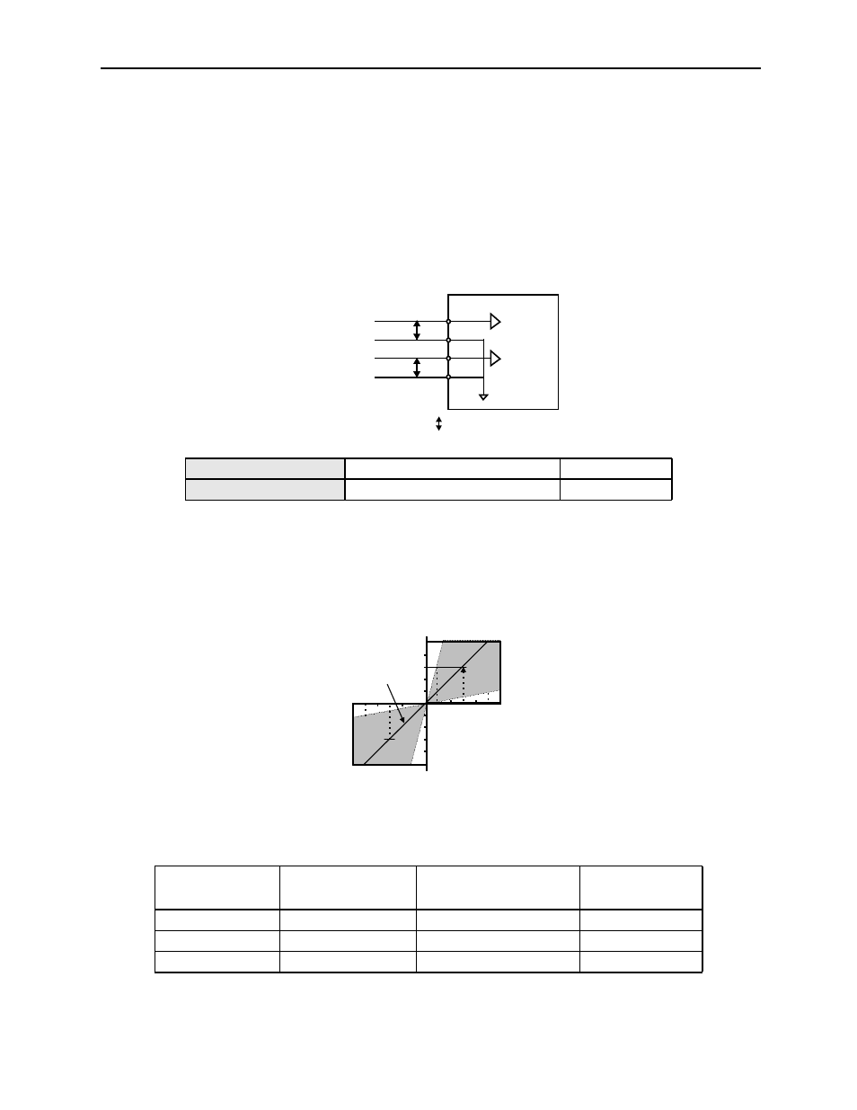
5.2.1
Speed Reference
Input the speed reference using the input signal Speed Reference Input. Since this
signal has various uses, set the optimum reference input for the system created.
The above inputs are used for speed control (analog reference). (Pn000.1 = 0, 4, 7,
9, or A).
Always wire for normal speed control.
Refer to 7.1.7 Operation in Monitor Mode
.
The motor speed is controlled in propor-
tion to the input voltage between V-REF and SG.
Setting Examples
Pn300 = 600: This setting means that 6V is equivalent to the rated motor speed.
Parameter Pn300 can be used to change the voltage input range.
Input V-REF CN1-5
Speed Reference Input
Speed Control
Input SG CN1-6
Signal Ground
Speed Control
Speed Reference
Input
Rotation Direction
Motor Speed
SGMAH
Servomotor
+6V
Forward rotation
Rated motor speed
3000rpm
+1V
Forward rotation
(1/6) rated motor speed
500rpm
-3V
Reverse rotation
(1/2) rated motor speed
1500rpm
Torque
reference
Speed
reference
CN1-9
CN1-10
CN1-5
CN1-6
SG
V-REF
SG
T-REF
Servo amplifier
Torque reference input
(analog voltage input)
Speed reference input
(analog voltage input)
P represents twisted pair wires.
P
P
Input voltage (V)
-4
-8
-12
4
8
12
Factory setting
Rated motor speed
Rated motor speed
The slope is set in Pn300.