Yaskawa Sigma II Series Servo System User Manual
Page 471
Sigma II User’s Manual
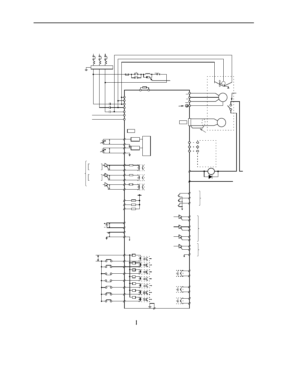
Appendix C: Examples of Standard Connections
C - 5
400V (22kW, 30kW)
Servomotor
Fan
U(A) V(B) W(C)
P
LPF*
P
LPF*
Photocoupler maximum output:
Operating voltage: 30V
DC
Operating current: 50mA
DC
Reference speed:
±2V to ±10V/rated speed (set by parameter)
Torque reference:
±1 to ±10V/rated torque (set by parameter)
Alarm code maximum output:
Operating voltage: 30V
DC
Backup battery 2.8 to 4.5V
(When using an absolute encoder).
SEN signal input
(When using an absolute encoder).
Operating current: 20mA
DC
P: Indicates twisted wire pairs.
1CN
PG
M
Noise filter
SGDH Servo Amplifier
Three-phase 380 to 480V
ac
(50/60Hz)
R
S
T
1MCCB
Power Power
1MC
1MC
1MC
SUP
Be sure to attach a
B1
B2
L1/R
L2/S
U
V
DC24P
DC24N
L3/T
W
V-REF
9
10
A/D
PULS
/PULS
PULS
P
SIGN
CLR
7
/SIGN
P
P
/CLR
8
11
12
15
14
150W
38
39
33
34
35
36
19
20
49
1
48
37
BAT (+)
P
SEN
SG
47
40
41
42
43
44
45
25
26
27
28
29
30
31
46
P
BAT (-)
+24V
+5V
0V
+24V
Used only with
an absolute encoder
Servo ON
Proportional (P) control
Forward run
Reverse run
Alarm reset
Forward current
/S-ON
/P-CON
P-OT
N-OT
ALM-RST
/P-CL
/N-CL
/V-CMP+
/T-GON+
/S-RDY+
/S-RDY-
/T-GON-
/V-CMP-
Reverse current
prohibited
prohibited
limit ON
limit ON
ALO1
ALO3
ALO3
PAO
/PAO
PBO
/PBO
PCO
/PCO
PSO
/PSO
SG
Amount of S-phase rotation
PG dividing ratio output
Be sure to properly
Optical
prepare the end of
encoder
Applicable line receiver
SN75175 or MC3486 manufac-
tured by T/I, or the equivalent
Serial data output
Applicable line receiver
SN75175 or MC3486 manufac-
tured by T/I, or the equivalent
Positioning completed
(ON when positioning is
completed)
T-GON output
Servo ready output
(ON at levels above the setting)
(ON when ready)
Connect shield to connector shell
Connector shell
Forward run prohibited with
Reverse run prohibited with
Alarm reset with 3Ry ON
P control with 2Ry ON
Reverse current limit ON with 7Ry ON
Forward current limit ON with 6Ry ON
N-LS OPEN
P-LS OPEN
Servo ON with 1Ry ON
Position reference
CW
CLR
Phase A
A (1)
B (2)
C (3)
D (4)
Be sure to
ground
OFF
ON
1Ry
ALM+
FG
5
6
(/COIN+)
(/COIN-)
Speed coincidence detection
(ON when speed coincides)
24V
DC
±15%
Regenerative Resistor
SG
T-REF
SG
1Ry
2RY
P-LS
N-LS
3Ry
6Ry
7RY
4.7k
Ω
the shielded wire.
1
1B
+24V
1Ry
1D
0V
ALM-
32
0V
+10
-15 %
24V
DC
+10% maximum
DU
DW
DV
Dynamic
Brake
*The time constant for the primary filter is 47
μs
2CN
SIGN
CCW
Phase B
surge suppressor to
the excitation coil of
the magnetic contactor
and relay.
0V
1k
Ω
PL1
PL2
3
13
18
PL3
+12V
Open-collector
reference
power supply
21
22
4
2
OV
380 ~ 480V
Note:The thermal protector must be wired
to provide protection in the event of
the motor overheating.
**Thermal
Protector