Yaskawa Sigma II Series Servo System User Manual
Page 61
Sigma II User’s Manual
Chapter 3: Wiring
3 - 23
See 3.5 Wiring Encoders (for SGMGH and SGMSH Motors Only) for con-
nection circuit examples.
•
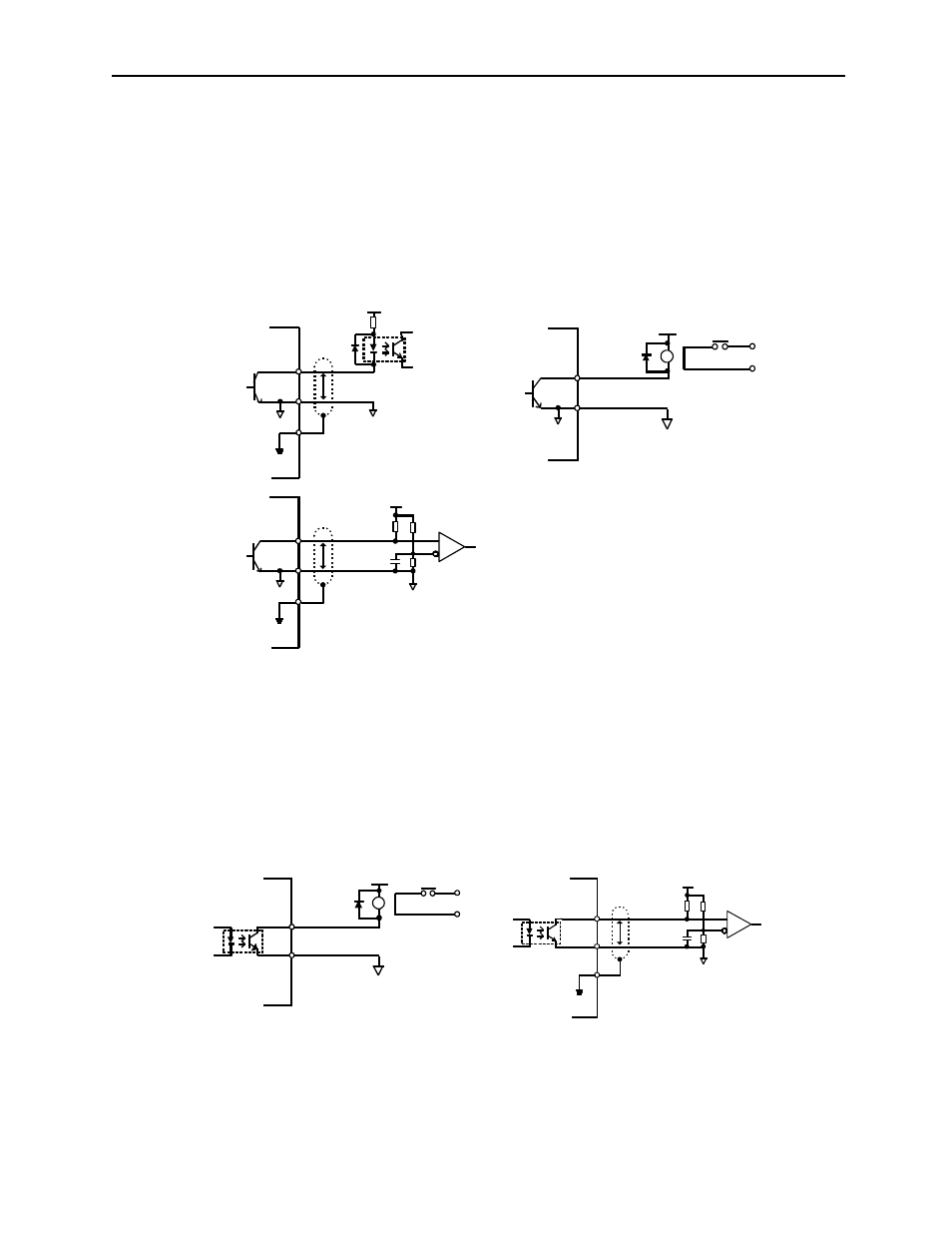
Connecting to an Open-collector Output Circuit
Alarm code signals are output from open-collector transistor output circuits.
Connect an open-collector output circuit through a photocoupler, relay, or line
receiver circuit.
Note: The maximum allowable voltage and current capacities for open-collector circuits are:
•
Voltage: 30V
DC
•
Current: 20mA
DC
•
Connecting to a Photocoupler Output Circuit
Photocoupler output circuits are used for servo alarm, servo ready, and other
sequence output signal circuits.
Connect a photocoupler output circuit through a relay or line receiver circuit.
Note: The maximum allowable capacities for photocoupler output circuits are:
•
Voltage: 30V
DC
•
Current: 50mA
DC
0V
P
0V
Photocoupler
Relay
0V
P
0V
0V
Servo amplifier
end
Servo amplifier
end
Servo amplifier
end
5 to 12V
DC
5 to 12V
DC
5 to 12V
DC
Line receiver
0V
P
0V
Relay
Servo amplifier end
5 to 12V
DC
Servo amplifier end
5 to 12V
DC