Output signal connections – Yaskawa Sigma II Series Servo System User Manual
Page 113
Sigma II User’s Manual
Chapter 5: Parameter Settings and Functions
5 - 27
Output Signal Connections
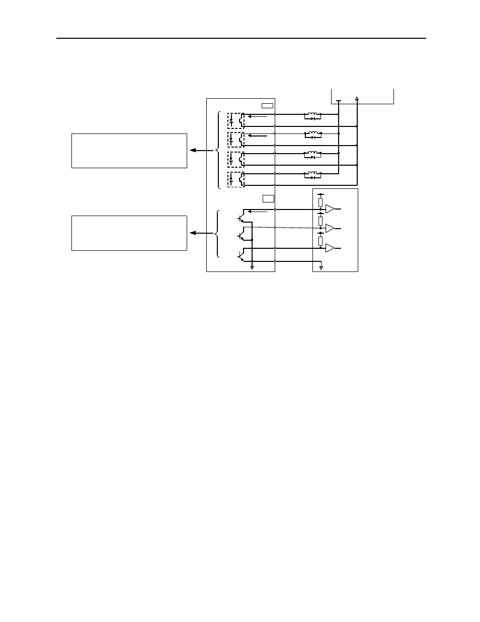
Connect the sequence output signals as shown in the following figure.
Note: Provide a separate external I/O power supply; the servo amplifier does not have an internal 24V
power supply. Yaskawa recommends using the same type of external power supply as that used for
input circuits.
Function allocation for some sequence output signal circuits can be changed.
See 5.3.4 Output Circuit Signal Allocation for more details.
0V
0V
Host controller
Servo amplifier
Photocoupler
50mA max.
31
CN1
32
25
26
27
28
29
30
ALM+
ALM-
V-CMP+
V-CMP-
TGON+
TGON-
S-RDY+
S-RDY-
50mA max.
20mA max.
37
38
39
1
ALO1
ALO2
ALO3
SG
CN1
I/O power supply
+24V
0V
~
~
~
~
Photocoupler output levels per output node:
• Maximum operating voltage: 30V
DC
• Maximum output current: 50mA
DC
Open collector output levels per output node:
• Maximum operating voltage: 30V
DC
• Maximum output current: 20mA
DC
CN1