Yaskawa Sigma II Series Servo System User Manual
Page 160
Sigma II User’s Manual
Chapter 5: Parameter Settings and Functions
5-74
Note See 5.3.3 Input Circuit Signal Allocation for other Pn50A.1 settings.
5.5.3
Using the Positioning Completed Output Signal (/COIN)
The basic use and wiring procedure for the positioning completed (/COIN) output
signal (photocoupler output signal) is described below. The signal is output to
indicate that servomotor operation is completed.
This signal indicates that servomotor movement has been completed during position
control. The host controller uses the signal as an interlock to confirm that
positioning is completed.
Pn50A.1
Setting
Status
Result
0
Enables the servo ON
(/S-ON) input signal.
The servo is OFF when CN-40 is open, and is ON when
CN1-40 is at 0V.
7
Disables the servo ON
(/S-ON) input signal.
The servo is always ON, and has the same effect as
shorting CN1-40 to 0V.
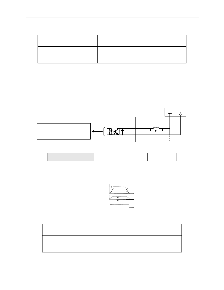
Output /COIN CN1-25
Positioning Completed Output
Signal
Position Control
/COIN
State
Status
Result
ON
Circuit between CN1-25 and 26 is
closed, and CN1-25 is at low level.
Positioning is completed. (Position
error is below the setting.)
OFF
Circuit between CN1-25 and 26 is
open, and CN1-25 is at high level.
Positioning is not completed. (Position
error is above the setting.)
CN1-25
CN1-26
/COIN+
/COIN-
+24V
0V
Servo amplifier
I/O power supply
P
hotocoupler output levels per output node:
• Maximum operating voltage: 30V
DC
• Maximum output current: 50mA
DC
Speed
Reference
Servomotor
/COIN
(CN1-25)
Pn500
Error pulse
(Un008)