2 typical main circuit wiring example, 3 cable specifications and peripheral devices, Typical main circuit wiring example -14 – Yaskawa Sigma II Series Servo System User Manual
Page 52: Cable specifications and peripheral devices -14, Designing a power on sequence
Sigma II User’s Manual
Chapter 3: Wiring
3 - 14
3.3.2
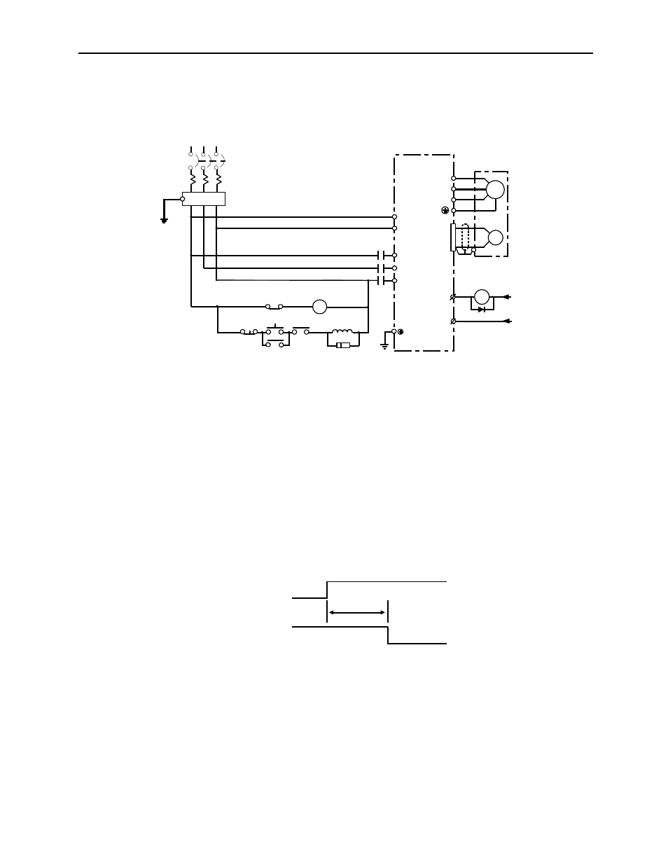
Typical Main Circuit Wiring Example
The following figure shows a typical example of main circuit wiring.
Designing a Power ON Sequence
Note the following when designing the power ON sequence.
Design the power ON sequence so that power is turned OFF when a servo alarm
signal is output. (See the circuit figure above.)
•
Hold the power ON button for at least two seconds. The servo amplifier will
output a servo alarm signal for two seconds or less when power is turned ON.
This is required in order to initialize the servo amplifier.
3.3.3
Cable Specifications and Peripheral Devices
Refer to the Sigma II Series Servo System Catalog Supplement (No. G-MI#99001).
1MCCB: Molded-case circuit breaker (for the inverter)
FIL: Noise filter
1MC: Contactor
1Ry: Relay
1PL: Indicator lamp
1SUP: Surge suppressor
1D: Flyback diode
M
FIL
1Ry
Main power supply
ON
1Ry
OFF
1MC
1MC
(For servo alarm display)
1SUP
1MC
L1
L2
L3
L1C
L2C
Servo Amplifier
U
V
W
A
B
C
D
PG
CN1
31
+24V
ALM
ALM-SG
32
1D
0V
1Ry
1MCCB
R
S
T
1PL
Main
power supply
SGDH-
AE
Power Supply
Servo alarm (ALM)
output signal
2.0s maximum