Yaskawa Sigma II Series Servo System User Manual
Page 98
Sigma II User’s Manual
Chapter 5: Parameter Settings and Functions
5 - 12
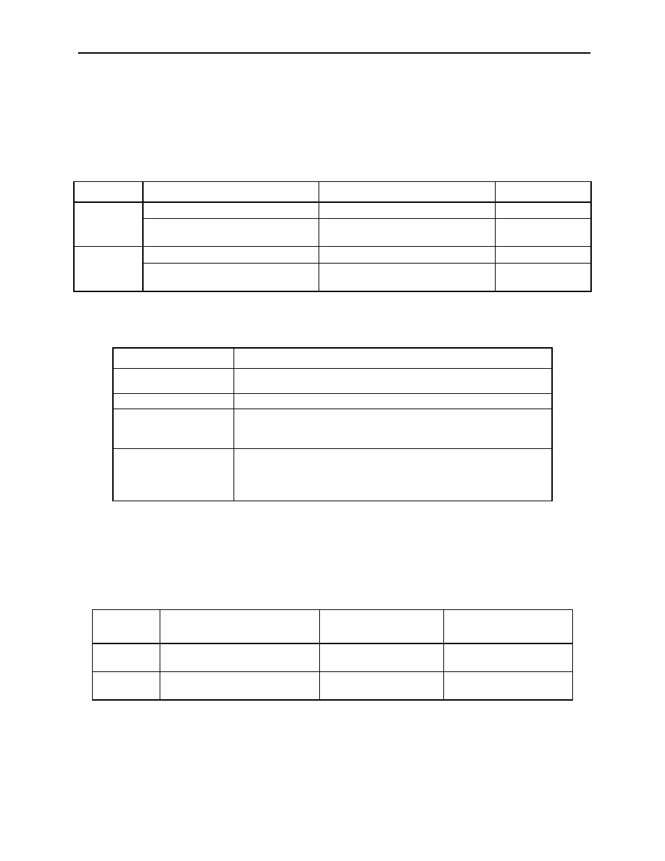
This is the external torque (current) limit input for forward and reverse rotation.
Check input signal allocation status when using this function. (See 5.3.3
Input Circuit Signal Allocation). Default settings are given in the table on
the following page.
The following output signals and monitor methods are used when torque is
being limited.
Application Examples:
•
Forced stop.
•
Robot holding a workpiece.
Parameter
Signal Status
Comments
Description
/P-CL
CN1-45 at low level when ON
Use forward torque limit.
Limit: Pn404
CN1-45 at high level when OFF
Do not use forward torque limit.
Normal operation.
—
/N-CL
CN1-46 at low level when ON
Use reverse torque limit.
Limit: Pn405
CN1-46 at high level when OFF
Do not use reverse torque limit.
Normal operation.
—
Signal
Description
/CLT
Generated when Pn50F.0 is allocated to an output terminal from SO1
to SO3.
Monitor Mode (Un006)
—
• Un005: Numbers 6
and 7 (With Default
Settings)
Refer to 7.1.7 Operation in Monitor Mode.
• Un006: Depending
on output signal
allocation condi-
tions.
—
Parameter
Signal
Setting
(%)
Control Mode
Pn404
Forward External Torque Limit
Range: 0 to 800
Default Setting: 100
Speed/Torque Control,
Position Control
Pn405
Reverse External Torque Limit
Range: 0 to 800
Default Setting: 100
Speed/Torque Control,
Position Control