Enabling/disabling input signals – Yaskawa Sigma II Series Servo System User Manual
Page 93
Sigma II User’s Manual
Chapter 5: Parameter Settings and Functions
5 - 7
Enabling/Disabling Input Signals
Set the following parameters to specify whether input signals are used for overtravel
or not. The default setting is “used.”
Servomotor Stop Mode for P-OT and N-OT Input Signals
Set the following parameters to specify the Servomotor Stop Mode when P-OT and
N-OT input signals are used.
Specify the Servomotor Stop Mode when either of the following signals is input
during servomotor operation.
•
Forward run prohibited input (P-OT,CN1-42)
•
Reverse run prohibited input (N-OT,CN1-43)
Parameter
Signal
Setting
Control Mode
Pn50A.3
P-OT Signal Mapping
(Forward Run Prohibit Input Signal)
Default Setting: 2
Speed/Torque Control,
Position Control
Pn50B.0
N-OT Signal Mapping
(Reverse Run Prohibit Input Signal)
Default Setting: 3
Speed/Torque Control,
Position Control
Parameter
Signal
Setting
Description
Pn50A.3
P-OT Signal Mapping
(Forward Run Prohibit
Input Signal)
Default Setting: 2
Uses the P-OT input signal to prevent forward
rotation. (Forward rotation is prohibited when
CN1-42 is open and is allowed when CN1-42 is
at 0V).
8
Does not use the P-OT input signal to prevent
forward rotation. (Forward rotation is always
allowed and has the same effect as shorting
CN1-42 to 0V).
Pn50B.0
N-OT Signal Mapping
(Reverse Run Pro-
hibit Input Signal)
Default Setting: 3
Uses the N-OT input signal to prevent reverse
rotation. (Reverse rotation is prohibited when
CN1-43 is open and is allowed when CN1-43 is
at 0V).
8
Does not use the N-OT input signal to prevent
reverse rotation. (Reverse rotation is always
allowed and has the same effect as shorting
CN1-43 to 0V).
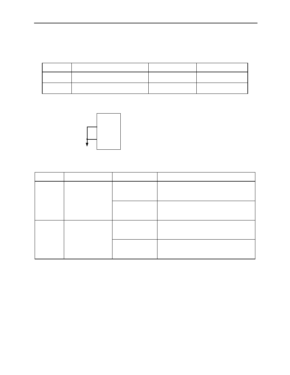
CN1-42
(P-OT)
CN-43
(N-OT)
0 V
The short-circuit wiring shown in the figure can be
omitted when P-OT and N-OT are not used.
Servo Amplifier