3 input circuit signal allocation, 3 input circuit signal allocation - 53, Input signal allocation – Yaskawa Sigma II Series Servo System User Manual
Page 139

Sigma II User’s Manual
Chapter 5: Parameter Settings and Functions
5-53
5.3.3
Input Circuit Signal Allocation
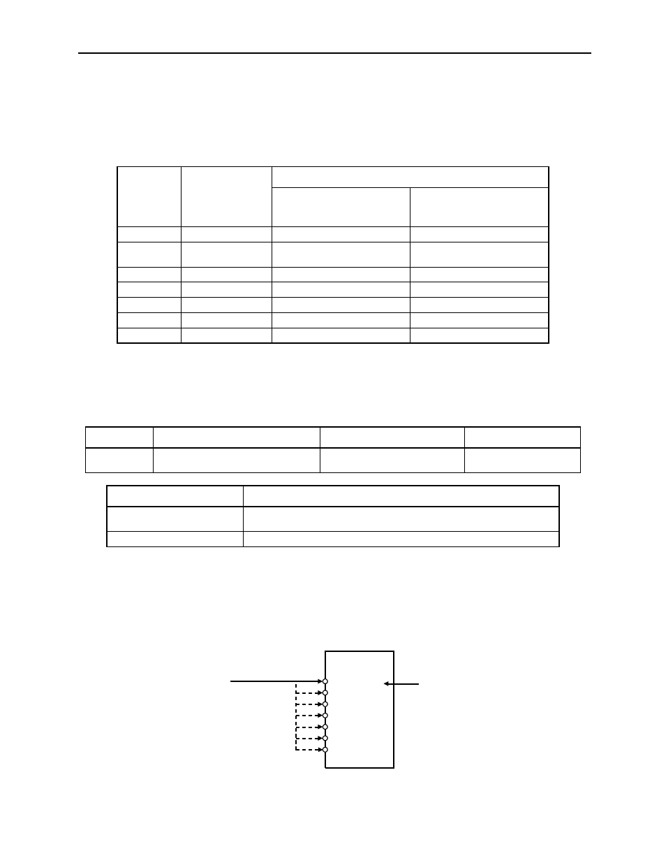
The functions allocated to sequence input signal circuits can be changed. CN1
connector input signals are allocated with the default settings as shown in the
following table.
Note: *
The functions of these input signals are automatically switched according to the setting at
parameter Pn000.1 as long as Pn50A.0 is set to 0.
The following parameter is used to enable input signal allocation.
Note: The default setting for parameter Pn50A.0 is 0. Functions and applications in this manual are
generally described for the factory defaults.
Input Signal Allocation
The following signal can be allocated when Pn50A.0 is set to 1.
CN1
Connector
Terminal
Numbers
Input Terminal
Name
Default Setting
Symbol
Name
40
SI0
/S-ON
Servo ON
41
SI1
/P-CON
(Proportional control refer-
ence) *
42
SI2
P-OT
Forward run prohibit
43
SI3
N-OT
Reverse run prohibit
44
SI4
/ALM-RST
Alarm reset
45
SI5
/P-CL
(Forward current limit) *
46
SI6
/N-CL
(Reverse current limit) *
Parameter
Signal
Setting
Description
Pn50A.0
Input Signal Allocation Mode
Default Setting: 0
Speed/Torque Control,
Position Control
Pn50A.0 Setting
Description
0
Default setting for sequence input signal allocation.
This setting is the same as Yaskawa SGDB- AD servo amplifiers.
1
Enables any sequence input signal settings.
40 (SI0)
41 (SI1)
42 (SI2)
43 (SI3)
44 (SI4)
45 (SI5)
46 (SI6)
Servo amplifier
CN1
Determines
terminal
allocation
for input
signals.
/S-ON
CN1-40 is default set for
the /S-ON input signal.
Any terminal from CN1-40 to
46 can be allocated to the
/S-ON signal through the
Pn50A.1 parameter.