Operating example, Speed reference used as detection point – Yaskawa Sigma II Series Servo System User Manual
Page 248
Sigma II User’s Manual
Chapter 6: Servo Adjustment
6 - 16
Torque Reference Input Used as Detection Point (Standard Setting)
With this setting, if the value of torque reference input exceeds the torque set in
parameter Pn10C, the speed loop switches to P control.
The servo amplifier is default set to this standard mode (Pn10C = 200).
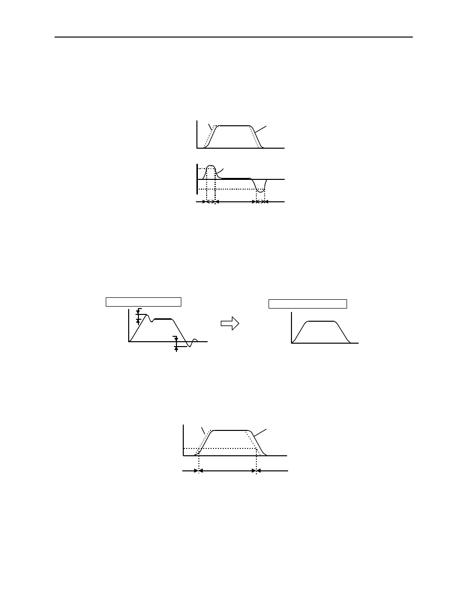
Operating Example
If the system is always in PI control without using the mode switch function, the
speed of the motor may overshoot or undershoot due to torque saturation during
motor acceleration or deceleration. The mode switch function suppresses torque
saturation and eliminates motor speed overshoot or undershoot.
Speed Reference Used as Detection Point
With this setting, if a speed reference exceeds the value set in parameter Pn10D, the
speed loop switches to P control.
Motor speed
Reference speed
Speed
Internal torque reference
+Pn10C
Torque 0
-Pn10C
PI control
PI control
PI control
P control
P control
Overshoot
Undershoot
Motor
speed
Time
No mode switch function
With mode switch function
Motor
speed
Time
Speed reference
Speed
Pn10D
Motor speed
Time
P control
PI
control
PI control