Addition of an outside interlock, Wiring example – Yaskawa Sigma II Series Servo System User Manual
Page 153
Sigma II User’s Manual
Chapter 5: Parameter Settings and Functions
5-67
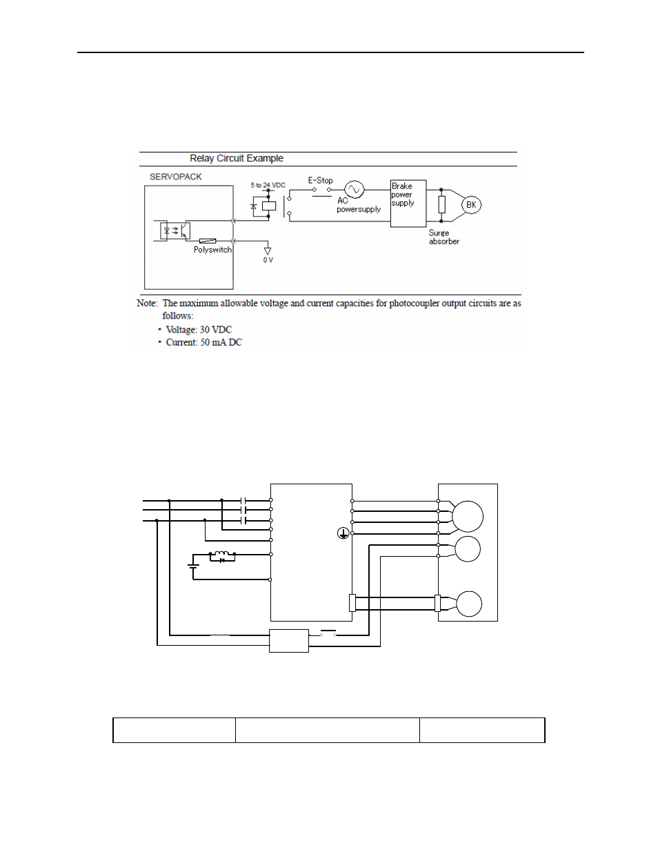
Addition of an outside interlock:
Safety can be enhanced by the addition of an interlock circuit.
Please examine the operation sequence of the emergency stop circuit in accordance
with your system requirements. Asuggested interlock circuit is shown below:
Wiring Example
Use the servo amplifier contact output signal /BK and the brake power supply to
form a brake ON/OFF circuit. The following diagram shows a standard wiring
example.
*CN1-1 /BK+ and CN1-2 /BK- are the output terminals allocated at parameter Pn50F.2.
Output /BK
Brake Interlock Output
Speed/Torque Control,
Position Control
M
BK
PG
Servomotor
with brake
A (1)
B (2)
C (3)
D (4)
E (5)
F (6)
U
V
W
CN2
Red
Black
Blue or
yellow
White
AC
DC
BK-RY
BK-RY
+24V
Brake Power Supply
Power supply
Servo amplifier
L1
L2
L3
L1C
L2C
CN1-1
CN1-2
/BK+*
/BK-*
(Provided by Customer)
BK-RY