6 using the servo ready output signal (/s-rdy), Using the servo ready output signal (/s-rdy) -79 – Yaskawa Sigma II Series Servo System User Manual
Page 165
Sigma II User’s Manual
Chapter 5: Parameter Settings and Functions
5-79
5.5.6
Using the Servo Ready Output Signal (/S-RDY)
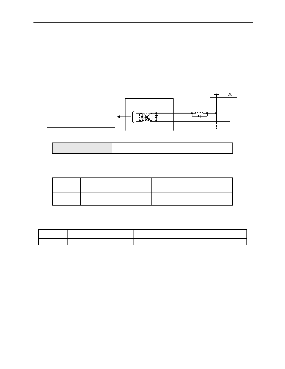
The basic use and wiring procedures for the Servo Ready (/S-RDY) output signal
(photocoupler output signal) are described below.
Servo Ready means there are no servo alarms and the main circuit power supply is
turned ON. An added condition with absolute encoder specifications is that the SEN
signal is at high level and absolute data was output to the host controller.
This signal indicates that the servo amplifier has completed all preparations and is
ready to receive the Servo ON signal.
The following parameter setting is used to change the CN1 connector terminal that
outputs the /S-RDY signal.
The parameter is factory set so the /V-CMP signal is output between CN1-29 and 30.
See 5.3.4 Output Circuit Signal Allocation for more details on parameter Pn50E.
Output /S-RDY CN1-29
Servo Ready Output Signal
Speed/Torque Control,
Position Control
/S-RDY
State
Status
Result
ON
Closed or low level.
Servomotor is ready.
OFF
Open or high level.
Servomotor is not ready.
Parameter
Signal
Setting)
Description
Pn50E
Output Signal Selections 1
Default Setting: 3211
Position Control
+24V
0V
Servo amplifier
I/O power supply
CN1-29 /S-RDY+
CN1-30 /S-RDY-
Photocoupler output levels per output node:
• Maximum operating voltage: 30V
DC
• Maximum output current: 50mA
DC