2 servo amplifiers, 2 servo amplifiers - 9, Servo amplifiers -9 – Yaskawa Sigma II Series Servo System User Manual
Page 27
Sigma II User’s Manual
Chapter 1: Checking Product and Part Names
1 - 9
1.2.2
Servo Amplifiers
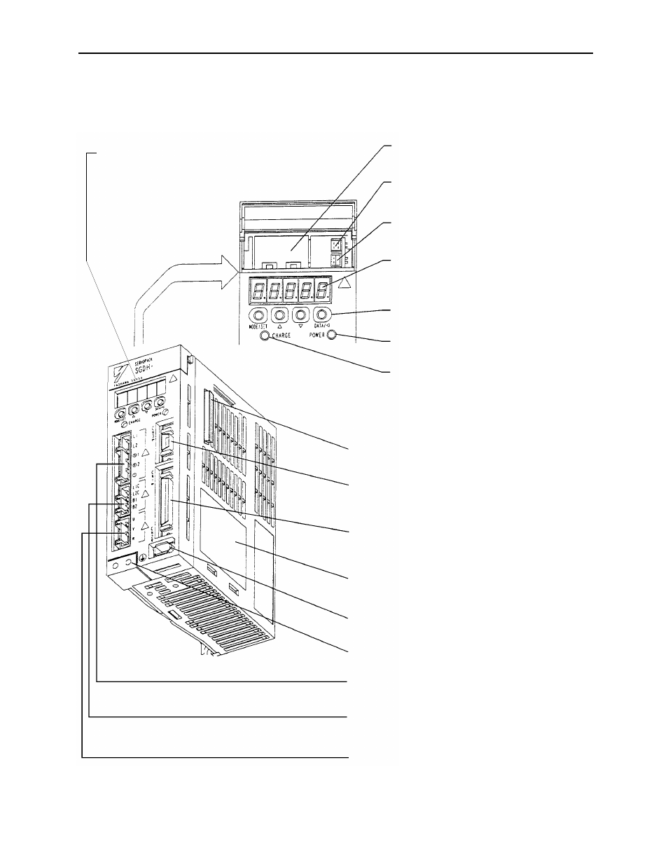
The figure below shows the part names for servo amplifiers.
Battery Holder
CN5 Analog Monitor Connector
CN8 Battery Connector
Panel Display
Panel Keys
Power ON Indicator
Charge Indicator
CN10 Connector for Option Unit
CN3 Connector to PC or Digital Operator
CN1 I/O Signal Connector
Nameplate
CN2 Encoder Connector
Ground Terminal
Main Circuit Power Supply Terminal
Control Power Supply Terminal
Servomotor Terminal
Used to house the backup battery for an
absolute encoder.
Used to monitor motor speed, torque refer-
ence, and other values through a special cable.
Used to connect to the backup battery for an
absolute encoder.
Five-digit 7-segment display panel used to
show servo status, alarm status, and other
values when parameters are entered.
Used to set parameters.
Lights when the control power supply is ON.
Lights when the main circuit power supply is
ON and stays as long as that component’s
capacitor remains charged. Therefore, if this
indicator is ON, do not touch the servo
amplifier, even after the power supply is
turned OFF.
Connects option units for expanding the amplifier’s functions.
Used to communicate with a personal computer or to
connect to an optional digital operator.
Used for both reference input and sequence I/O signals.
Indicates the servo amplifier model and its specific ratings.
Connects to the encoder in the servomotor.
Must be connected to protect against electrical shock.
Used for the main circuit power supply input.
Connects to the control power supply and to externally
mounted regenerative resistor (where applicable).
Connects to the servomotor power line.
Version Number
Indicates the Servo Amplifier hardware version and
software version (See "Amplifier Version Number").