Yaskawa Sigma II Series Servo System User Manual
Page 438
Sigma II User’s Manual
Appendix A: Host Controller Connection Examples
A - 6
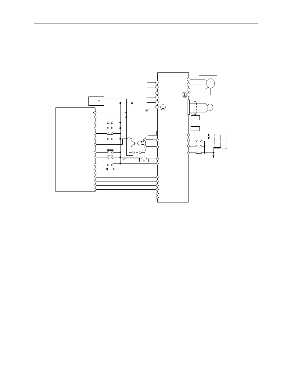
A.5 Connecting OMRON's C500-NC112 Position Control Unit
The following diagram shows an example of connecting to the OMRON C500-NC112
Position Con trol Unit. In this example, the servo amplifier is used in the position control
mode.
*1. The ALM signal is output for approximately two seconds when the power is turned
ON. Take this into consideration when designing the power ON sequence. The ALM
signal actuates the alarm detection relay 1Ry to stop main circuit power supply to the
servopack.
*2. Set the user parameter Pn200.0 to 1.
*3. Manufactured by Yaskawa Controls Co.
Note Only signals applicable to OMRON’s C500NC112 Position Control Unit and
Yaskawa’s SGDM servo amplifier are shown here.
CN1
CN2
+
-
+12V
I/O Power Supply
C500NC112
(Made by OMRON)
+12V
CW LIMIT
CCW LIMIT
EMERGENCY STOP
ORIGIN
ORIGIN PROXIMITY
LOCAL
READY
+5V
PULSE OUTPUT
1A
4A
3B
3A
2B
2A
1B
10B
10A
9B
9A
8B
8A
5B
5A
4B
4Ry
3Ry
1Ry
+5 V
+24V
8 7
12V
*
1
6 LRX01/A2
*3
012 V
+24VIN
POT
NOT
SON
10
9
31
32
20
19
15
12
11
8
7
14
47
43
42
40
3Ry +24 V
4Ry
1Ry
CN1
0V
EXTERNAL
INTERRUPT
Servopack
SGDM
L1C
L3
L2
L1
L2C
PC
O
*PCO
ALM+
ALM-
PULSE
CLR
SIGN
*PULSE
*CLR
*SIGN
012 V
M
PG
W
V
U
A (1)
B (2)
C (3)
D (4)
Servomotor
*2
External
power
supply
+24 V
*4
(Made by OMRON)
+24V
+
-
+12V
CW LIMIT
CCW LIMIT
EMERGENCY STOP
EXTERNAL
INTERRUPT
ORIGIN
ORIGIN PROXIMITY
LOCAL
READY
+5V
PULSE OUTPUT
10A
10B