Servo amplifier ratings and specifications table 2 – Yaskawa Sigma II Series Servo System User Manual
Page 370
Sigma II User’s Manual
Chapter 8: Ratings and Characteristics
8 - 40
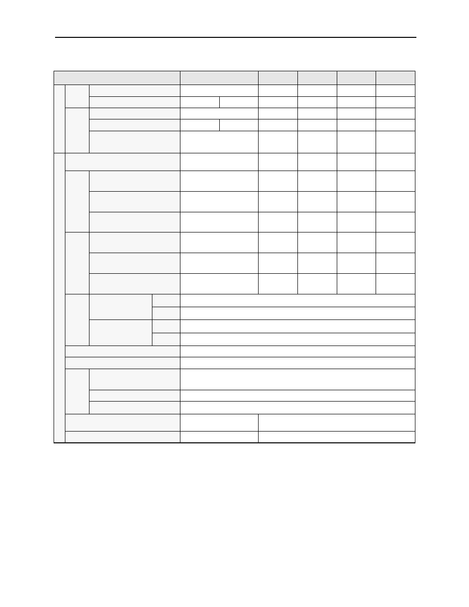
Servo Amplifier Ratings and Specifications Table 2
Notes:
*1
Supply voltage must not exceed 230V +10% (253V) or 115V + 10% (127V). A step-down
transformer is required if the voltage exceeds these values.
*2
Use the servo amplifier within the ambient temperature range. When enclosed, internal
temperatures must not exceed the specified range.
Servo Amplifier Model SGDH-
50
60
75
1A
1E
Appl
ica
ble
Servo
m
oto
r
20
0V
SGMGH- A A
44
55
75
1A
1E
SGMSH- A
40
50
—
—
—
—
400V
SGMGH- D
44
55
75
1A
1E
SGMSH- D
40
50
—
—
—
—
SGMUH- D
40
—
—
—
—
Ba
sic
Spec
ific
ati
ons
Maximum Applicable Servomotor Capacity
[kW]
5.0
6.0
7.0
11
15
200V
Continuous Input Current
[A
rms
]
24
32
41
60
80
Continuous Output Current
[A
rms
]
32.9
46.9
54.7
58.6
78.0
Maximum Output Current
[A
rms
]
84
110
130
140
170
400
V
Continuous Input Current
[A
rms
]
14.9
17.8
22.3
32.7
44.6
Continuous Output Current
[A
rms
]
16.5
21.1
27.4
28.1
37.2
Maximum Output Current
[A
rms
]
40.5
55
65
70
85
Inpu
t
Power
Supp
ly
*1
Main Circuit
200V
Three-phase 200 to 230V
ac
+10 to -15%, 50/60Hz
400V
Three-phase 380 to 480V
ac
+10 to -15%, 50/60Hz
Control Circuit
200V
Single-phase 200 to 230V
ac
+10 to -15%, 50/60Hz
400V
24V
DC
±15%.
Control Method
Three-phase full-wave rectification IGBT-PWM (sinewave driven)
Feedback
Serial encoder: 17-bit (incremental/absolute).
Condition
s
Ambient/Storage
Temperature
*2
0 to +55°C/-20 to +85°C
Ambient/Storage Humidity
90% relative humidity or less (with no condensation)
Vibration/Shock Resistance
4.9 m/s
2
/19.6 m/s
2
Configuration
Base mounted (Rack
mounted optional).
Base mounted. (Duct ventilated optional)
Approximate Mass For 200V lb. (kg)
12.1(5.5)
33.1 (15)