5 analog monitor, 5 analog monitor - 42, 5 analog monitor -42 – Yaskawa Sigma II Series Servo System User Manual
Page 274

Sigma II User’s Manual
Chapter 6: Servo Adjustment
6 - 42
6.5 Analog Monitor
The analog monitor can be used to observe a variety of analog voltage signals.
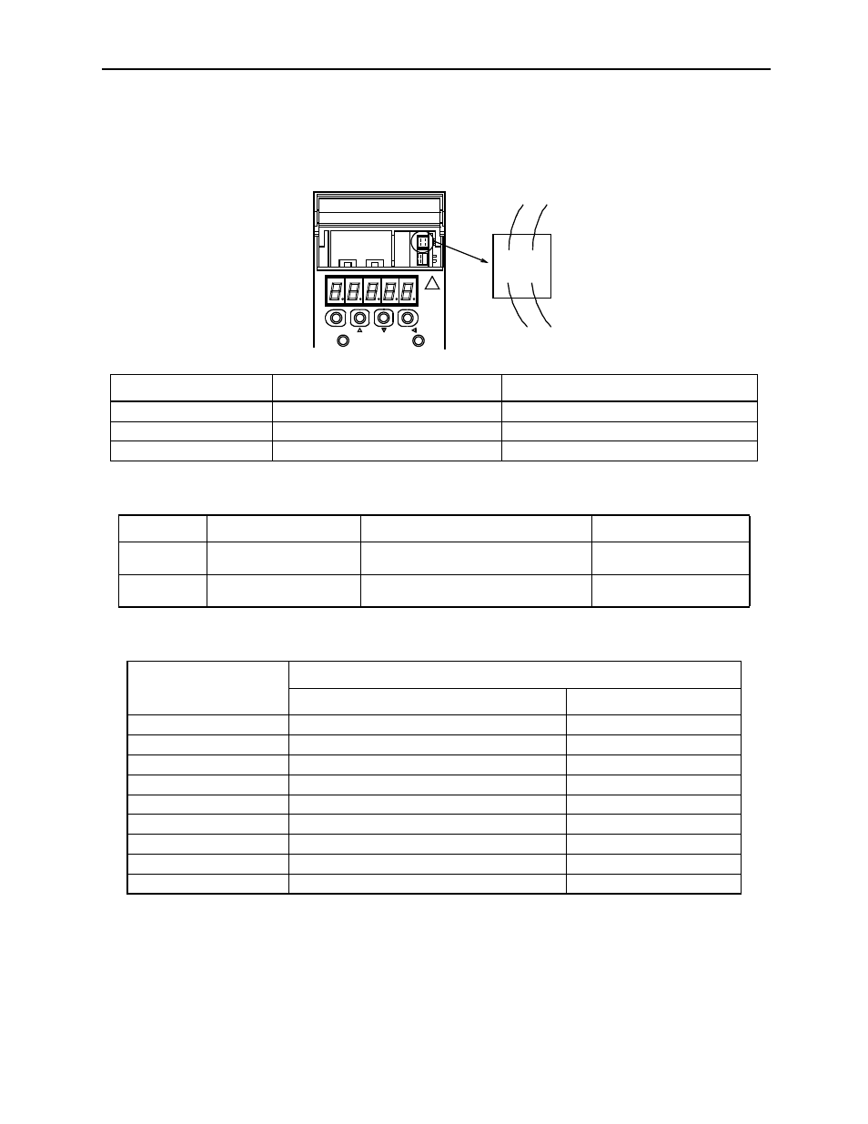
Analog monitor signals must be observed through the CN5 connector using the
DE9404559 cable.
Analog monitor signals can be selected with parameters Pn003.0 and Pn003.1.
The following monitor signals can be observed.
Note: 1. In the case of torque or speed control mode, the position error monitor signal has no meaning.
2. The output voltage range of the analog monitor is ±8V maximum. The polarity of the output voltage
will be changed if ±8V is exceeded.
Cable Color
Signal Name
Description
White
Analog monitor 1
Torque reference: 1V/100% rated torque
Red
Analog monitor 2
motor speed:1 V/1000rpm
Black (two wires)
GND (0V)
—
Parameter
Signal
Setting
Description
Pn003.0
Analog Monitor 1
Default Setting: 2
Speed/Torque Control,
Position Control
Pn003.1
Analog Monitor 2
Default Setting: 0
Speed/Torque Control,
Position Control
Settings in Pn003.0
and Pn003.1
Description
Monitor signal
Observation gain
0
Motor speed
1V/1000rpm
1
Speed reference
1V/1000rpm
2
Torque reference
1V/100% rated torque
3
Position error
0.05 V/1 reference unit
4
Position error
0.05 V/100 reference unit
5
Reference pulse frequency (converted to rpm)
1V/1000rpm
6
Motor speed
1V/250rpm
7
Motor speed
1V/125rpm
8 - E
Reserved monitor signal
—
MODE/SET
CHARGE
DATA/
POWER
CN5
Red White
Black Black